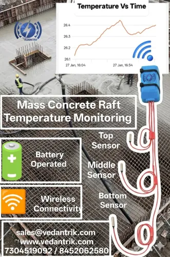

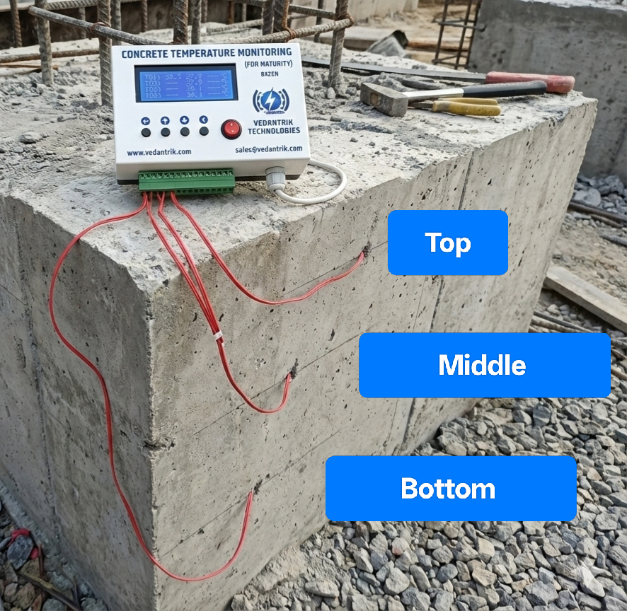
Thermocouple installation for mass concrete temperature monitoring at the Top Bottom Middle to monitor the temperature differential, an advanced Temperature Monitoring system for mass concrete developed and manufactured by Vedantrik Technologies in India.
Mass concrete differs from ordinary concrete not because of the mix design, but because of the difference in their thermal behavior over time, which becomes a critical parameter to be regulated when volume is large. Specifically in mass concrete, the heat generated from cement hydration accumulates internally faster than it can dissipate in the environment due to the large volume and low surface-to-volume ratio.
At the same time the outer surface loses heat to the environment which then creates a temperature gradient (core hotter than surface) that results in thermal stress. If not quickly and efficiently regulated, such stress can cause severe thermal crack development, and compromise the durability, structural continuity, and long-term performance.
Guidance from ACI’s mass concrete practice (e.g., ACI 207.1R-05) emphasizes that the defining characteristic of mass concrete is this thermal behavior that is the need to manage heat generation and volume change due to hydration.
Special attention must be given to such thermal gradient zones by implementing Mass concrete temperature monitoring Methods to precisely map such zones and implement the necessary preventive measures to avoid compromisations with durability, strength maturity and structural integrity.
Monitoring the temperature differential in mass concrete is critical to control thermal stresses and prevent cracking caused by the heat of hydration. The goal is to capture the maximum thermal gradient between the hottest part of the concrete (core) and the coolest parts (top and bottom surfaces).
Industry Standard: According to ACI 301 / ACI 207, the temperature differential between the core and surface should be limited to prevent thermal cracking:
ΔTmax ≤ 19∘C
Sensor Placement Strategy
Temperature monitoring is not just about measuring single points; it is about capturing the vertical thermal gradient at the thickest section of the concrete element.
A. Middle Sensor (Core)
- Purpose: Measures the peak heat of hydration. This is typically the hottest part of the concrete.
- Location: Place at the geometric center of the pour (mass centroid).
- Example: For a 2.0 m thick raft foundation, install the middle sensor at 1.0 m depth.
B. Top and Bottom Sensors (Surfaces)
- Purpose: Measure how fast heat is escaping to the air or ground. These are the coolest points in the section.
- Placement: Do not place at the very surface. Sensors should be embedded slightly inside the concrete to measure actual material temperature, not ambient air.
- Standard Depth: 50 mm (~2 inches) from the exterior formwork or surface.
- Top Sensor: 50 mm below the finished top surface.
- Bottom Sensor: 50 mm above the mud mat or PCC.
Because concrete pouring is a vigorous process, there is a risk of cables breaking. For reliability, it is recommended to install two sensors at each location (a primary and a backup).
Installation Procedure
Step 1: Preparation and Routing
Thermocouple wires should be securely attached to the rebar cage using nylon or plastic zip ties. Avoid using metal tie wire on uninsulated sensors, as this can affect readings or create grounding issues. For protection, route the wires along the underside of the rebar (“shadow method”) to shield them from falling concrete and vibrations caused by compaction. Leave a small service loop near the sensor tip so that accidental tugs do not dislodge it.
Step 2: Top-Middle-Bottom Layout
- Bottom Sensor:
- Tie to the bottom reinforcement mat.
- Ensure the sensor tip is floating in the concrete cover zone (~50 mm above the mud mat) and not touching the base.
- Middle Sensor:
- If there is no rebar in the geometric center, install a vertical support bar (“chair”) to hold the sensor at the correct depth.
- Top Sensor:
- Tie to the top reinforcement mat.
- Angle the sensor tip upward to position it 50 mm below the finished top surface.
- Mark the location with high-visibility tape on the rebar to prevent accidental cutting by finishers.
Step 3: Exit and Labeling
- Bundle all sensor wires and route them to a safe station outside the formwork.
- Label both ends of each wire immediately (e.g., “Loc-A Middle,” “Loc-A Top”).
- Unlabeled wires are useless once buried.
Monitoring and Data Collection
Thermocouples are connected to a data logger or monitoring system, with readings recorded at regular intervals, typically every 15–30 minutes. This allows tracking of the peak temperature, temperature rise and fall rate, and the vertical temperature gradient. By comparing the measured differential to the allowable limit (ΔTmax ≤ 19∘C), engineers can determine if additional cooling or insulation measures are required.
Applications
This installation method is used in dams, raft foundations, large slabs, pile caps, and other high-volume concrete structures, where thermal cracking is a major concern. Proper installation ensures reliable, continuous temperature monitoring, effective thermal stress management, and improved durability of mass concrete structures.