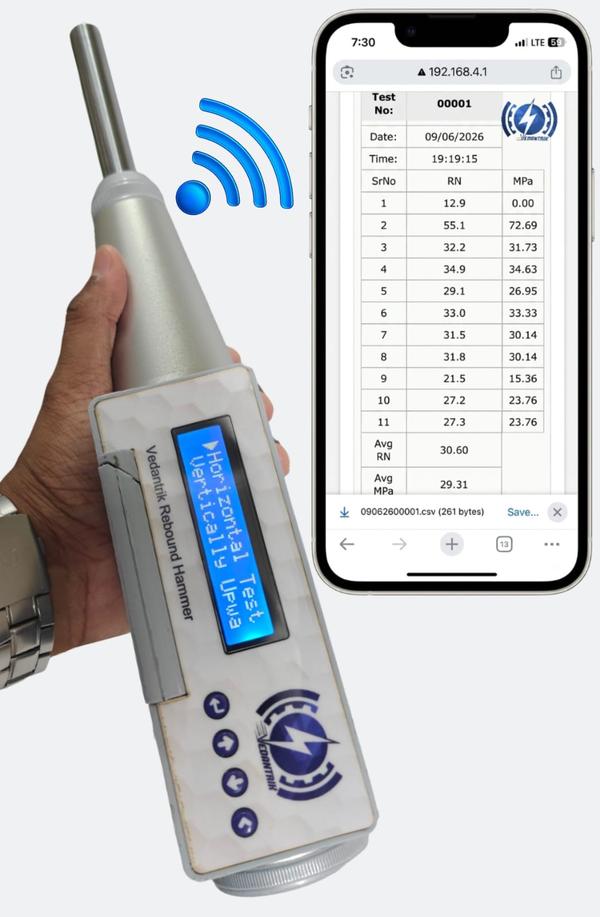
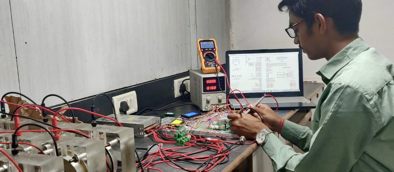
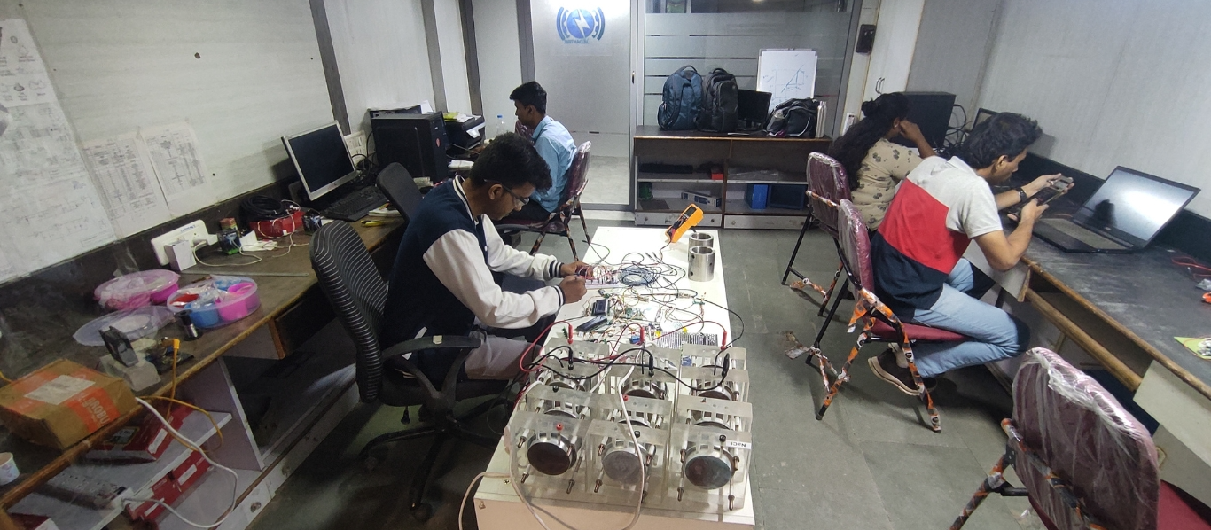
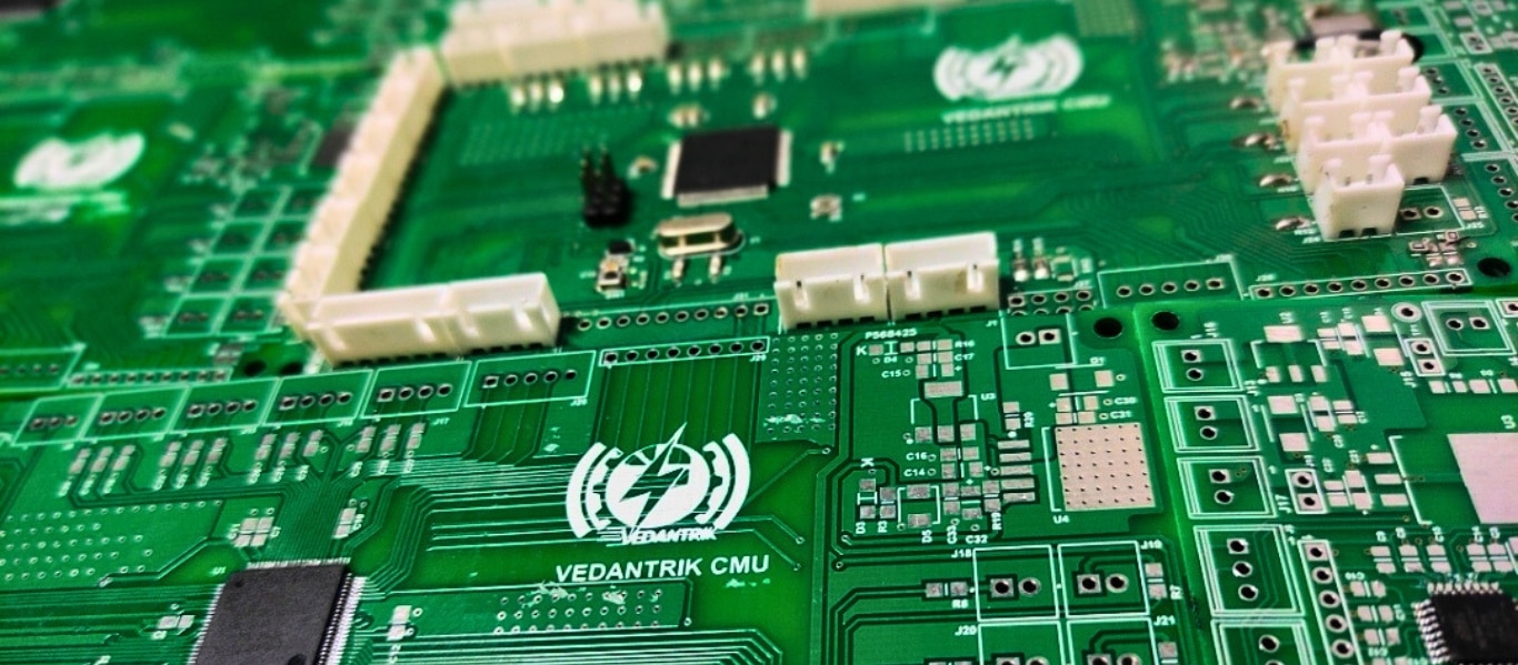
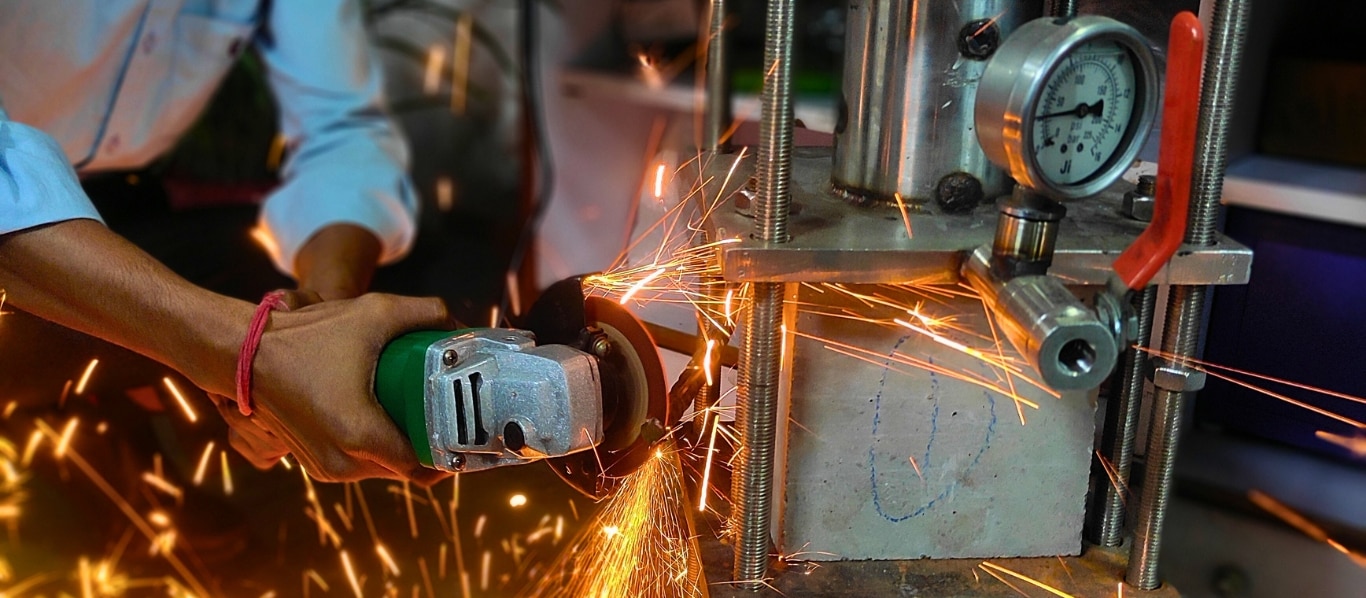
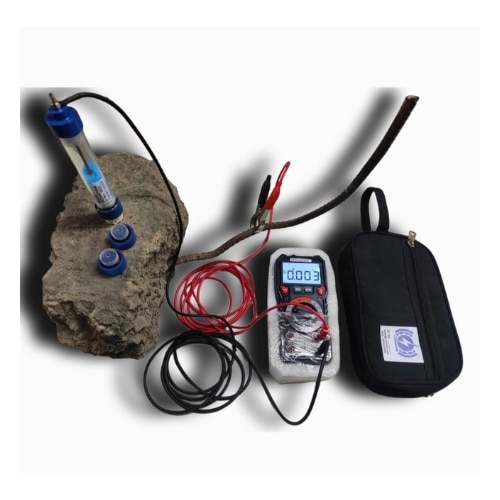
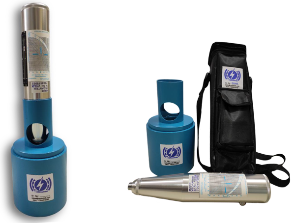
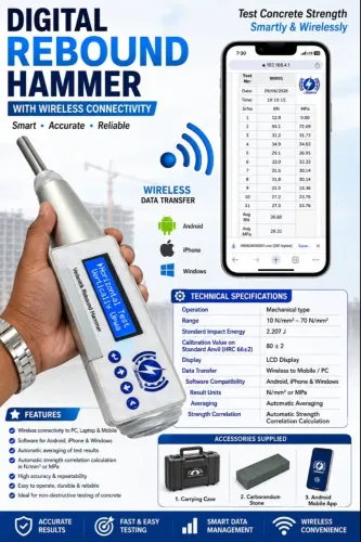
Mumbai
+917304519092
+917304519092

Vedantrik Technologies

about-cover-bg image
About Vedantrik Technologies

The Best Engineering And Scientific Equipments Manufacturers in mumbai

Products
Featured Products

What We Do

6814772a5d263414004dd4a4 Card 2

product image
Curing Tank Temperature Controller

Curing Tank Temperature Controller for Concrete Cubes NABL Calibrated | Single & Three Phase | Waterproof & Shockproof | Heater, Chiller & Pump Ready Vedantrik Technologies presents an advanced curing tank temperature controller designed specifically for concrete cube curing tanks used in NABL-accredited laboratories, RMC plants, construction site labs, and infrastructure projects. The system accurately maintains the standard curing temperature of 27 ± 2 °C, as prescribed by IS and NABL guidelines. Equipped with an intelligent temperature controller, SS316 waterproof immersion heaters, and built-in electrical safety protections, this solution eliminates manual temperature monitoring and ensures consistent, audit-compliant curing conditions. Each system can be supplied with an NABL-traceable calibration certificate, making it suitable for laboratory audits and quality assurance processes. Concrete Curing Tank Temperature Control System This plug-and-play curing tank controller manages heating during winter and cooling during summer, ensuring uninterrupted and uniform curing of concrete test specimens. The controller supports both single phase and three phase power supplies, allowing it to work seamlessly with different tank sizes and heater configurations without any modification. Ideal Applications Concrete cube curing tanks NABL civil engineering laboratories Construction site testing laboratories RMC plants and QA/QC departments Infrastructure and government projects Technical Specifications – Curing Tank Controller Power Supply: Single Phase / Three Phase AC, 230 V Maximum Current Capacity: 32 Amps Temperature Set Point: 27 ± 2 °C Temperature Accuracy: ±1 °C Controller Power Cord Length: 2 meters Temperature Sensor Cable Length: 5 meters Plug & Play Connections Heater connection Chiller connection Water circulation pump connection Temperature sensor connection No skilled installation required. Key Features of Curing Tank Temperature Controller Compatible with single phase and three phase heaters Dedicated socket for chiller (summer curing) Dedicated socket for circulation pump Built-in short circuit and over-current protection Integrated MCB and RCCB for complete electrical safety Rugged design suitable for laboratory and onsite conditions Smart Heating & Cooling Logic (Energy Efficient) Heating Control – Winter Operation Heater switches OFF above 27 °C Heater switches ON below 25 °C Prevents overheating and reduces power consumption Chiller Control – Summer Operation Chiller switches ON above 29 °C Chiller switches OFF below 25 °C Maintains curing temperature as per NABL and IS standards Heater Selection Based on Curing Tank Volume Below 2000 liters: Single phase heater recommended Above 2000 liters: Three phase heater recommended The controller supports both heater types without any modification. Electrical Load Capacity of Controller Three Phase Heater Load Heater Rating: 4 kW per unit Minimum Load: 1 × 4 kW Maximum Load: 4 × 4 kW (Total 16 kW) Single Phase Heater Load Heater Rating: Up to 2 kW per unit Minimum Load: 1 heater Maximum Load: 3 heaters (Total 6 kW) Note: Single phase heaters draw higher current; therefore, lower total power is recommended. For large curing tanks, three phase heaters provide better efficiency and stability. SS316 Waterproof & Shockproof Immersion Heaters Three Phase Immersion Heater Power Rating: 4 kW Cable Length: 5 meters Cable Type: 5-core Heater Material: SS316 Protection: Waterproof & shockproof Single Phase Immersion Heater Power Rating: 2 kW Cable Length: 5 meters Cable Type: 3-core Heater Material: SS316 Protection: Waterproof & shockproof Recommended Heater Configuration for Curing Tanks Single Phase System (Small & Medium Tanks) 2000 liters: 1 × 2 kW heater 4000 liters: 2 × 2 kW heaters 6000 liters: 3 × 2 kW heaters Maintains 27 ± 2 °C curing temperature. Three Phase System (Large Tanks) Up to 2500 liters: 1 × 4 kW heater Up to 5000 liters: 2 × 4 kW heaters (8 kW) Up to 7500 liters: 3 × 4 kW heaters (12 kW) Up to 10,000 liters: 4 × 4 kW heaters (16 kW) Best Practices for Uniform Concrete Curing Interconnect multiple curing tanks using a water circulation pump For identical tanks in the same environment, one temperature sensor is sufficient For different tank sizes, place the sensor in the largest tank Use multiple controllers for independent temperature control Multichannel curing tank controller available for economical multi-tank operation NABL Compliance & Custom Solutions NABL-traceable temperature calibration certificate available Multichannel and customized curing tank controllers Designed for NABL labs, RMC plants, infrastructure projects, and site laboratories Contact for Pricing & Technical Support 📞 8452062580 📧 sales@vedantrik.com Topic covered above Curing tank temperature controller Concrete cube curing tank controller NABL curing tank temperature controller Concrete curing tank heater SS316 immersion heater for curing tank Single phase curing tank heater Three phase curing tank heater Concrete laboratory curing equipment Curing tank temperature control system

6814772a5d263414004dd4a4 Card 2

product image
Concrete Maturity meter

Vedantrik Technologies is first in India to develop and manufacture Sacrificial type Wireless Concrete Maturity Meter, which monitors temperature, maturity, and strength. Using Vedantrik Maturity Meter Per Point testing is 7-10 times Cheaper compared to any Imported or Re-usable type Maturity Meter Multi-Channel Sensing : Monitor Top, Middle, and Bottom concrete temperatures using a single Maturity Meter. Wireless Type: No cable routing, Seamlessly connect with mobile phones or laptops. On-Board Data Storage: Temperature, maturity, and strength data stored in inbuilt memory—download anytime. In-Built Battery Powered: No 24×7 external power supply required. No Expensive Reader Required: Your smartphone becomes the reader and monitor. ✔ True 3-in-1 Monitoring Temperature • Maturity • Strength — in one device. Sacrificial & Damage-Proof: Designed to be embedded—no special handling or protection needed. Lowest Cost per Point: More economical than reusable maturity meters. Low Capital Investment: Eliminates high upfront cost of reusable wired systems. Ideal for Multi-Location Projects: Deploy multiple sensors across sites without wiring or complexity. Smart sensing. Lower cost. Scalable deployment. Concrete Maturity meter is a device inserted in concrete structure while casting, to monitor the concrete maturity and strength of the actual concrete by measuring temperature variations within the concrete, the device calculates the maturity value to develop a co-relation between maturity and strength, enabling real-time strength monitoring of both precast and cast-in-place concrete and also useful for determining the correct time for foam work or shuttering removal and to decide when to stretch the tendons in PT Slabs. Vedantrik Technologies has developed India’s first Wireless type Concrete Maturity meter and installed it in India’s first bullet train Project at BKC. Concrete Maturity meter is available in various models like wireless and wired type, Sacrificial and Reusable type concrete maturity meter where only the sensor will be sacrificed and the transmitter part can be reused as per the different different application, concrete maturity meter for Concrete Road and infrastructure Projects, residential project and mass concrete temperature monitoring, temperature differential and for thermal gradient monitoring is also available. The temperature sensors are embedded into the concrete at the construction site to measure temperature continuously. The maturity value is then calculated based on the recorded temperature data and correlated with the concrete strength. This correlation must be established for the specific concrete mix design As per ASTM C1074 standards and remains valid as long as the mix design does not change. to Know more write on sales@vedantrik.com or Whatsapp 8452062580 Principle behind Concrete Maturity Measurement Method: The concrete maturity method is an empirical technique employed to predict the development of strength in concrete as a function of its temperature-time history. The fundamental principle underlying this method is that the rate of cement hydration process, along with the consequential strength gain, is not only influenced by the age of the concrete since the time of casting, but primarily by the combined effect of time and temperature. In essence the maturity method is useful in quantifying the degree of hydration by integrating temperature over time, thereby allowing to estimate the strength of in-situ concrete with great accuracy, especially during the early stages of curing. Concrete strength gain is intrinsically linked to the kinetics of cement hydration, a complex exothermic reaction between water and cementitious materials such as tricalcium silicate, dicalcium silicate, tricalcium aluminate, and tetracalcium aluminoferrite that leads to formation of calcium-silicate-hydrate (C-S-H) gel and other reaction products that contribute materials structural integrity. The rate of these hydration reactions are temperature dependent, so elevation in temperature increases the rate, mainly because of reduced activation energy barrier, while lower temperatures affect it in the opposite manner. However, this same hydration process can result in excessive heat generation that has a direct effect on the morphology and distribution of the hydration products. Hence, it can lead to temperature induced changes in the micro-structures, porosity and micro-cracking due to differential thermal gradients, especially in mass concrete. Furthermore elevated temperature can also affect the natural evolution of the micro-structures in the concrete, thereby affecting the structural and mechanical properties beyond that could be assessed by the maturity method. Nurse-Saul Method: The common approach for estimation of concrete’s strength from its maturity, utilizes the Nurse-Saul method, which assumes that there is a linear relationship between temperature and the rate of hydration. The general formula proposed is expressed in the form given below: M(t) = ∑ (Ta - T0) * Δt Where : M(t) = the temperature-time factor at age t, degree-days or degree-hours, Δt = a time interval, days or hours, Ta = average concrete temperature during time interval, Δt, °C, and To = datum temperature, °C. Arrhenius Method: The hydration process can halt altogether if the concrete remains below datum temperature, as it can be assumed that datum temperature sets a critical temperature threshold limit. Crossing this limit creates a condition where maturity is no longer linear and cannot be predicted until other supplementary cementitious mixtures (SCM) such as accelerators are added into the mix. In such cases where ambient temperature goes below datum temperature (0°C for India) the Arrhenius method gives a more accurate and reliable result. The Arrhenius method is based on activation energy that captures nonlinear temperature effects more accurately, especially under extreme hot or cold conditions.The general formula proposed is expressed in the form given below: te = ∑e-Q(1/Ta - 1/Ts) * Δt Where: te = equivalent age at a specified temperature Ts, days or h, Q = activation energy divided by the gas constant, K, Ta = average temperature of concrete during time interval Dt, K, Ts = specified temperature, K, and Δt = time interval, days or h. Measurement of Maturity and strength: Nurse-Saul function is the widely used method, which assumes that there is a linear relationship between temperature and the rate of hydration. The general formula is expressed in the form given below: M(t) = ∑ (Ta - T0) * Δt Where : M(t) = the temperature-time factor at age t, degree-days or degree-hours, Δt = time interval, days or hours, Ta = average concrete temperature during time interval, Δt, °C, and To = datum temperature, °C. After calculating the maturity values for each of the specified curing days and determining the corresponding compressive strengths from the CTM (Compression Testing Machine) results, plot a graph of maturity index versus compressive strength. Fit a trend-line to the data to identify the best-fit relationship, typically a logarithmic regression provides a good representation of the strength development in relation to maturity. Fc = a + b * log10 (M) Components of Concrete Maturity Method: Temperature Monitoring Equipment - Devices to measure and record concrete temperature over time. Concrete Strength Testing - Standard strength tests (e.g., ASTM C39 – Compressive strength of cylindrical concrete specimens). Reference Temperature - A specific temperature used in maturity calculations. For Nurse–Saul, the typical reference is 0°C (32°F) unless otherwise specified. Concrete Mix Design Information - The maturity method is mix-specific; a separate calibration curve is required for each mix. Data Collection and Analysis Tools - Software or spreadsheets to calculate maturity and estimate strength. Ensures real-time tracking and reporting. Components of Concrete Maturity Method: Temperature Monitoring Equipment - Devices to measure and record concrete temperature over time. Concrete Strength Testing - Standard strength tests (e.g., ASTM C39 – Compressive strength of cylindrical concrete specimens). Reference Temperature - A specific temperature used in maturity calculations. For Nurse–Saul, the typical reference is 0°C (32°F) unless otherwise specified. Concrete Mix Design Information - The maturity method is mix-specific; a separate calibration curve is required for each mix. Data Collection and Analysis Tools - Software or spreadsheets to calculate maturity and estimate strength. Ensures real-time tracking and reporting. Standard procedure: Overview (as per ASTM C1074) 1. Objective of Maturity Method Calibration (Co-Relation Establishment) The primary objective of the calibration process in ASTM C1074 is to establish a reliable relationship between concrete maturity and its compressive strength for a specific concrete mix. This relationship—called the strength–maturity curve—enables users to estimate in-place concrete strength based on temperature history rather than destructive testing. Since the maturity method is mix-specific, each unique concrete mixture requires its own calibration. 2. Selection and Preparation of Concrete Mix The calibration begins by selecting the specific concrete mix that will be used in the field. This includes confirming the materials, proportions, and mixing procedure. Fresh concrete from this mix is then used to cast a set of standard specimens depending on the project requirements, which will be cured and tested over time to develop the strength–maturity relationship. 3. Temperature Monitoring of Specimens To track the maturity development, thermocouples or temperature sensors are embedded in at least two of the cylinders immediately after casting. These sensors record the internal temperature of the specimens continuously over time. The temperature data is used to calculate the maturity index using either the Nurse–Saul function or the Arrhenius function, as specified in ASTM C1074. 4. Curing and Strength Testing Schedule The concrete specimens are cured under standard laboratory conditions, and are tested for compressive strength at multiple time intervals; for example, at 1, 3, 7, 14, and 28 days. The specific times should span the range of expected strengths during field monitoring. At each test age, the corresponding maturity index is calculated based on the recorded temperature history. 5. Developing the Strength–Maturity Relationship After collecting the strength and maturity data at each age, the results are plotted with concrete strength on the y-axis and maturity index on the x-axis. A best-fit curve (usually exponential or logarithmic) is applied to the data points to define the strength–maturity relationship for the given concrete mix. This curve becomes the foundation for estimating in-place strength based on measured maturity in the field. Result Interpretation of Concrete Maturity Method: Result interpretation in the maturity method involves comparing the maturity index (°C·hours or °C·days) calculated from the in-situ concrete to a previously developed calibration curve that relates maturity to compressive strength. By identifying the maturity value measured in the field and locating that point on the calibration curve, the corresponding compressive strength can be estimated. This allows for a reliable prediction of the in-place concrete strength at any given time, provided the conditions match those used during calibration. When maturity and strength relation established becomes invalid If Mix design changes. (Cement/Admixture/Chemicals/etc) calibration becomes invalid ,This can be considered as advantage instead of disadvantage, like if mix design changes, maturity vs time response will vary. Co-relation established in winter will not be valid in summer or vice versa. Ambient condition (do not insert concrete cube in curing Tank at the time of co-relation establishment as the actual concrete structure can not be immersed in curing tank) Small concrete used during Co-relation establishment, hence this co-relation will not be valid for Mass-Concrete due to Thermal-Gradient Topics Covered above: Concrete Maturity, Concrete Maturity Method, Concrete Maturity Meter, Concrete Maturity Testing, Maturity Method Concrete Strength, Maturity Sensor for Concrete, Concrete Strength Maturity Curve, Nurse-Saul Maturity Formula, Temperature & Time Factor Method Concrete Maturity, Strength vs Maturity Relationship, How To Calibrate Concrete Maturity, Weighted Maturity Function Concrete, ASTM C1074 Maturity Method, Datum Temperature Concrete Maturity, Concrete Maturity Monitoring System, Temperature Sensor in Concrete Maturity, Real Time Concrete Maturity Monitoring, Maturity In Mass Concrete, Concrete Strength Monitoring using concrete maturity meter

6814772a5d263414004dd4a4 Card 2

product image
Calibration rod

Calibration Rod for UPV: Calibration rods used in the Ultrasonic Pulse Velocity (UPV) test is a crucial tool to ensure that the readings obtained from concrete specimens are accurate and reliable. According to IS 516 (Part 5/Sec 1): 2018, the calibration of the UPV apparatus is performed using standard calibration rods of known lengths and material properties. These rods are made of a homogeneous, dense, and isotropic material, whose Ultrasonic pulse velocity values are well established. The calibration process generally involves the use of two standard rods, where the first rod labeled 25 μs, is used for initial calibration of the equipment. The second rod labeled 100 μs is then used to verify the accuracy of calibration. By checking the transit time through this 100 μs rod, engineers can confirm whether the equipment remains correctly calibrated across a wider range of travel time. During calibration, the transmitting and receiving transducers are placed at the two ends of the calibration rod using a coupling medium such as grease or petroleum jelly to remove any air pockets that may tamper with the actual results and to also ensure good acoustic contact. A pulse is then transmitted through the rod, and the transit time is recorded, this mode of operation is called through transmission mode. Furthermore, the time measurement is then verified with reference time labeled on the rods to confirm the calibration. This dual-rod system (25 μs and 100 μs) ensures that the UPV equipment is not only initially calibrated but also verified for linearity and consistency over different travel times. It confirms that the instrument’s internal timing circuit and transducers function correctly across the expected range of measurements. As per IS 516 (Part 5/Sec 1): 2018, such calibration and verification must be performed before and after each series of tests, or whenever there is any suspicion of instrument drift or malfunction. Purpose of Calibration Rod: a) To ensure measurement reliability – Calibration rods ensure that subsequent UPV readings on concrete are valid and dependable. b) To check equipment accuracy – Ensures the UPV apparatus gives correct time readings before testing concrete. c) To detect instrument errors – Identifies any malfunction or timing error in the transducers or electronic timer. Principle behind Calibration: The use of calibration rods in UPV testing is fundamentally based on the principle of elastic wave propagation through homogeneous and isotropic media. The calibration rod serves as an excellent reference medium, having well characterized elastic and geometric properties, which allows for consistent verification of accurate time measurement capability of the UPV instrument. They behave like an idealized medium for propagation, with minimal internal scattering, negligible attenuation, and uniform acoustic impedance. When an ultrasonic pulse is transmitted through the rod, the longitudinal wave propagates along a predictable path, and the received signal exhibits well-defined wavefront characteristics. Since the UPV technique determines the pulse velocity V from the ratio of the known path length L to the measured transit time T (i.e., V=L/T), the accuracy of velocity calculation critically depends on the precision of time measurement and the stability of the transducer–instrument system. Any systematic deviation in the time registration or transducer response will introduce errors in the final velocity calculation, which can lead to misinterpretation of concrete quality and durability. Therefore, the calibration rod provides a standard benchmark against which such instrumental deviations can be identified and corrected. Components: a) Reference Rod (25 μs): Used to establish a standard calibration range for the accuracy of time measurement in the UPV apparatus. b) Reference Rod (100 μs): Utilised to confirm the validity and consistency of calibration across a longer propagation path length. Standard Procedure: Overview 1) Inspect the UPV instrument, ensuring all components are functional. Select clean reference bars, typically short (25 µs) and long (100 µs), free of surface defects. 2) Apply an appropriate coupling agent (e.g., petroleum jelly or glycerol paste) to the transducer faces and bar surfaces to ensure efficient ultrasonic energy transfer and prevent signal distortion. 3) Place the transducers on the short reference bar and measure the transit time. Compare with the known value (25 µs); any deviation beyond ±0.5% indicates the need for adjustment. 4) Repeat the measurement on the long reference bar (100 µs) to confirm linearity and consistency across longer path lengths. 5) If both measurements fall within tolerances, the instrument is calibrated and ready for field testing. Any discrepancies must be corrected before concrete testing. Factors influencing the Calibration Process: 1) Instrument Accuracy and Stability: The electronic timing system, pulse transmitter and the receiver must be stable and precise. Any drift or noise in the electronics can affect the measured transit time,leading to calibration error. 2) Transducer performance: Variation in transducer sensitivity, frequency , or wear can influence pulse generation and reception, affecting the measured time. Calibration ensures these effects are accounted for. 3) Coupling Quality: The efficiency of energy transfer between transducer and calibration rod and uniformity of the coupling agent. Poor coupling can reduce signal amplitude or introduce timing errors. 4) Transducer Alignment and Pressure: Misalignment or inconsistent contact pressure can change the effective path of the pulse, introducing errors in timing measurement during calibration. Accurate calibration is the foundation for every reliable Ultrasonic Pulse Velocity test. Even minor errors in time measurement can lead to inaccurate interpretation of the concrete’s quality. Therefore, to ensure precision and repeatability, calibration must be carried out using a standard reference. Vedantrik Technologies provide high quality calibration rods, made from Poly-methyl Methacrylate, which behaves as an excellent medium, providing acoustic stability, homogeneity, with minimal internal scattering, negligible attenuation, and isotropic properties. These calibration rods are available in two standard configurations: a short rod (25 µs) for calibration and a long rod (100 µs) for verification and validating timing consistency over extended paths. By acting as trusted standard reference, Vedantrik Calibration rods help eliminate measurement error that may otherwise compromise the true results.For efficient and reliable UPV calibration rods in Mumbai, contact Vedantrik Technologies and ensure the highest standards of concrete quality. As a best Ultrasonic pulse velocity Meter calibration rod Manufacturer in India we have supplied in Mumbai, Pune, Nashik, Aurangabad, Surat, Vadodara, Ahmedabad, Indore, Bhopal, Nagpur, Jaipur, Ludhiana, Ghaziabad, Delhi, Lucknow, Kanpur, Prayagraj, Patna, Ranchi, Dhanbad, Bengaluru, Hyderabad, Chennai, Coimbatore, Madurai, Visakhapatnam, Kolkata, and Srinagar. Also we have supplied a range of products in Dubai, Abu Dhabi, the United Arab Emirates, Oman, Saudi Arabia, Kuwait, and Iran. We also serve clients in Singapore, Indonesia, Thailand, and other international locations.

Have any custom requirements?

Image Gallery

Pictures That Speak