

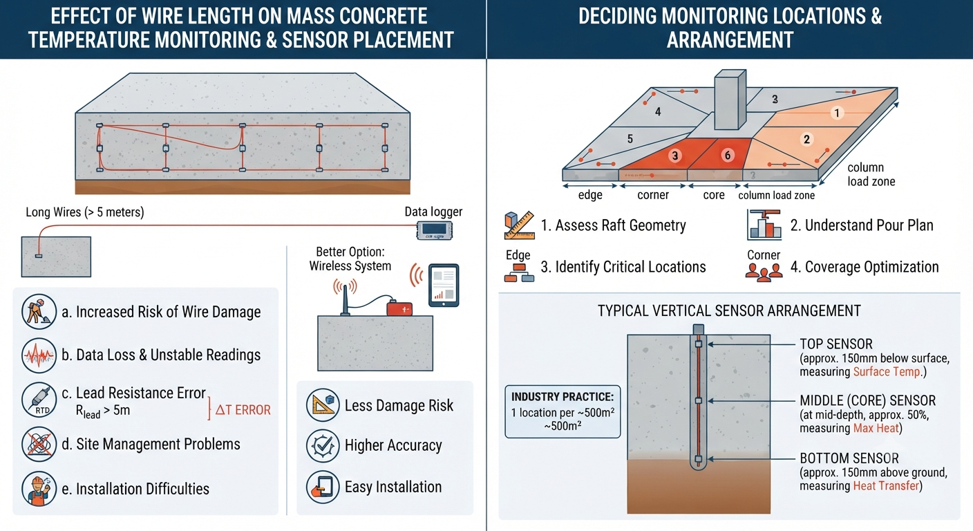
Wire length plays a very important role in mass concrete temperature monitoring. In raft foundations, pile caps, dams, and other large concrete pours, thermocouples or RTD sensors are connected to a data logger using wires. If the wire length is too long, it can affect both accuracy and site handling.
a. Increased Risk of Wire Damage
Long wires spread across the construction site are more likely to get damaged during work. Activities like concreting, reinforcement fixing, and vibration can easily cut or disturb the cables. Even small damage can lead to loss of temperature data or incorrect readings, which affects quality control decisions.
b. Data Loss and Unstable Readings
Long wire connections are more exposed to electrical noise and site disturbances. This can cause unstable temperature readings or sudden fluctuations. In some cases, temporary data loss may also happen. Since temperature monitoring is used for critical decisions like de-shuttering, accurate and stable data is very important.
c. Lead Resistance Error in RTD Sensors (Important Point)
In RTD systems, wire length directly affects accuracy due to lead resistance. When wire length increases beyond around 5 meters, the resistance of the wire starts influencing the reading. This leads to an error where the system shows a higher temperature than the actual concrete temperature. This type of error can affect thermal analysis and decision-making if not properly compensated.
d. Site Management Problems
Long wires on site create practical difficulties. They can block movement of workers, get tangled with reinforcement steel, and create safety hazards. They also make the site look untidy and difficult to manage, especially during large pours with multiple sensors.
e. Installation Difficulties
Long wire systems require careful planning, routing, and protection. This increases installation time and effort. There is also a higher chance of human error during setup. In fast-paced construction projects, this can delay monitoring readiness before concreting starts.
f. Better Option – Short Wire or Wireless Systems
To avoid these issues, modern systems use short wire connections or wireless monitoring technology. These systems reduce the risk of damage, improve accuracy, and make installation much easier.
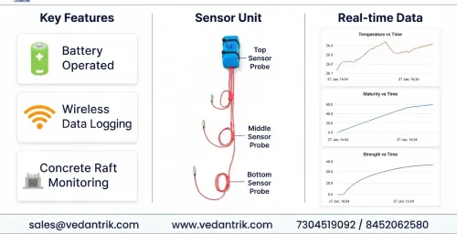
Vedantrik Technologies provides Wireless and Battery-Operated Mass Concrete Temperature Monitoring Systems where the monitoring device is placed near the sensor. This ensures accurate Top, Middle, and Bottom temperature readings, eliminates long cable runs, and provides real-time data without interruption.
7. How to Decide the Number of Locations for Mass Concrete Temperature Monitoring
Deciding the number of temperature monitoring locations in mass concrete is important to properly understand heat development and temperature variation inside the structure. It helps in controlling thermal cracking and ensuring safe construction of raft foundations, pile caps, dams, and other large concrete elements. The number of locations depends on raft size, thickness, geometry, and construction sequence.
Assessment of Raft Geometry
The first step is to study the raft geometry from approved structural drawings. This includes thickness, overall plan area, and total volume of concrete. Larger and thicker rafts generate more heat and show higher temperature differences, so they require more monitoring locations compared to smaller rafts.
Understanding Pour Plan and Sequence
The pour plan and sequence of concrete placement must be carefully studied. This includes segmentation of pours, construction joints, and vertical joints. The raft is divided into different pour blocks, and each block should be represented by at least one monitoring location to properly capture temperature behavior.
Identification of Critical Monitoring Locations
Critical monitoring points are selected on the raft plan. At each location, sensors are installed in a vertical alignment at three levels:
- Top sensor
- Middle (core) sensor
- Bottom sensor
This arrangement helps in understanding temperature variation from surface to core.
Basis for Selection of Critical Locations
Selection of monitoring points should be done in consultation with the structural consultant or concrete technologist. Key factors include raft thickness, structural layout such as columns and shear walls, load concentration zones, and expected thermal restraint conditions. Areas with higher stress or heat buildup should always be prioritized.
Segmentation Based on Pour Sequence
The raft is divided into segments based on the pour sequence and construction joints. The central point (centroid) of each segment is identified and selected as a monitoring location. This ensures proper coverage of all construction zones and uniform temperature tracking.
Coverage Optimization
Additional monitoring points may be added to improve coverage, especially in:
- Large raft areas
- Irregular shapes
- Zones with varying thickness
- Areas with different restraint conditions
This helps in getting a more accurate temperature profile of the entire structure.
Edge and Corner Considerations
Edges and corners lose heat faster because they are exposed to surrounding air on more sides. These areas often show higher temperature differences compared to the core. Therefore, at least one monitoring location should be placed near edges or corners to capture this variation properly.
Guidelines for Number of Monitoring Locations
There is no strict codal rule defining the exact number of monitoring points based on raft size. However, as a general industry practice:
- One monitoring location is considered per ~500 m² of raft area
This can be adjusted based on project requirements, consultant recommendations, structural importance, and budget considerations.
Sensor Installation Arrangement
At each monitoring location, sensors are installed vertically at three levels:
- Top sensor: placed approximately 150 mm below the top surface to measure surface temperature
- Middle (core) sensor: placed at mid-depth (around 50% of raft thickness), where maximum heat is expected
- Bottom sensor: placed approximately 150 mm above the bottom surface to monitor heat transfer to the ground.