Thank you for writing to us. One of our executive will reach back to you through your submitted medium. In case there’s an urgency, feel free to connect over WhatsApp for faster response.
Prefer calling? Dial +918043694111 (International callers) or 08043694111 (Indian callers).
About Half cell potential test:
The half cell potential test is a widely utilised, non-destructive electrochemical technique used primarily for assessing the likelihood of the corrosion activity in steel reinforcement. It is especially designed to evaluate the electrochemical potential of steel reinforcement embedded in concrete by comparing it to the reference electrode placed on the surface. The test serves as an indirect method of estimating the corrosion activity, without physically damaging the structure or extracting reinforcing bar (rebar).
When the steel corrodes in concrete, it undergoes oxidation reaction, releasing electrons. These electrochemical processes generate a measurable potential difference between the embedded steel and the reference electrode. In a half cell test, a high impedance voltmeter is used to measure this potential difference , which reflects the electrochemical state of the steel. The reference electrode, typically a copper/copper sulfate (Cu/CuSO4) or a silver/silver chloride (Ag/AgCl), provides a stable known potential against which the steel’s potential can be compared. The steel reinforcement, if corroding, will show negative potential due to the anodic reactions taking place on its surface.
For analysis of the obtained value it becomes necessary to understand the significance of the measured potential. According to the standards like ASTM C876, a potential value measurement that is more negative than -350 mV generally indicates high probability of corrosion activity occurring at the time of measurement. It is important to note that the test only reflects the potential of corrosion at the time of testing and does not quantify the rate and the extent of corrosion damage. Several factors can influence the test accuracy and its interpretation. Moisture content plays an important role, as higher moisture content naturally increases the ionic conductivity of the concrete. Surface conditions, such as coatings or contaminants can affect electrical conductance or measurement accuracy.
Purpose of half cell potential test:
1. To detect whether corrosion activity of the steel reinforcement is actively occurring.
2. To assess the probability of corrosion in the steel reinforcement.
3. To locate corrosion prone areas across the concrete surface
4. Monitor the effectiveness of protection measures.
Principle of half cell potential test:
The half-cell potential test is based on the principle that the steel reinforcement embedded within the concrete matrix behaves as an electrochemical phase capable of participating in redox processes at the steel-concrete-pore solution interface. When a metallic electrode such as reinforced steel is immersed in a conductive medium an equilibrium is established between the metallic iron phase and its ionic species (Fe2+, Fe3+) present in the adjacent pore solution. This equilibrium gives rise to measurable potential difference, referred as half-cell potential, which reflects the thermodynamic tendency of the embedded steel to undergo oxidation or reduction.
The underlying principle lies in the distribution of electrochemical potential at the interface between the embedded steel and the electrolyte contained within the concrete's pore structure. Concrete contains a microscopic network of interconnected pores filled with an aqueous ionic solution consisting of hydroxyl ions, alkali metals cations (Na+, K+), and dissolved oxygen and carbonates. The equilibrium potential near the steel depends on the redox state of the steel surface, ionic composition of the pore solution, and physicochemical properties of the surrounding medium.
When the steel reinforcement surface is under a high alkaline environment with pH values above 12.5, the surface of the steel is covered by a thin, adherent, and protective oxide film, primarily composed of Fe2O3 or Fe3O4. This protective layer drastically reduces the rate of anodic dissolution of the iron , and the steel's potential stabilizes at a relatively nominal value (I.e., less negative value). Conversely when aggressive species such as chloride ions penetrate the concrete cover or when carbonation lowers the local pH below the threshold of passivity, this protective film becomes thermodynamically unstable. The destruction of the protective film exposes the metallic surface of the steel to direct electrochemical interaction with the pore solution, initiating the active corrosion processes characterized by the anodic dissolution of the iron into Fe2+ and Fe3+ ions. In the context of reinforced concrete, the steel does not exist as an isolated bar; rather, it constitutes a distributed electrochemical network within heterogeneous electrolytes in the concrete. The electrical continuity of the rebar and ionic conductivity of the pore solution enables establishment of galvanic cells across the concrete structure. Within such systems, spatial variations in moisture content, oxygen availability, chloride concentration and pH give rise to localized anodic and cathodic regions. Hence the half-cell potential represents the mixed potential resulting from these competing electrochemical reactions, primarily the oxidation of iron at the anodic sites and reduction of water or oxygen at cathodic sites.
When measuring the electrochemical potential difference between the rebar and reference electrode which is typically as copper/copper sulfate or silver/silver chloride electrode, the concrete acts as an ionic conductor that facilitates the charge transport between the steel and the reference electrode. The measured potential is therefore an indirect reflection of the thermodynamic force for corrosion reaction occurring at the steel surface. A more negative potential corresponds to a greater tendency of anodic dissolution (i.e., active corrosion).
The heterogeneous nature of concrete adds further electrochemical intricacy. Variations in pore structure, degree of saturation, and electrical resistivity across the concrete matrix causes the spatial potential gradients that are not solely attributed to corrosion activity but also the transport properties of the medium. The resistivity of the concrete governs the internal potential drop between the steel and the surface, the moisture and temperature affects the mobility of the ionic species. Hence the half-cell potential shows an integrated electrochemical response encompassing thermodynamic equilibrium, inter-facial kinetics, and ion transport across the phase.
Measurement of Half-cell potential test:
Measurements are generally taken on a grid pattern with spacing between 0.25m and 1.0m, depending on the required mapping resolution. The concrete surface should be moist to ensure proper electric contact, which is maintained using a wet sponge or conductive gel under the electrode.
The value of potential difference (E) measured is expressed in Volts (V), more commonly recorded in millivolt with respect to reference electrodes.
Components of Half-cell potential test:
1. Reference Electrode: Provides a stable, known potential for comparison. Common types include Cu/CuSO₄ for soil and Ag/AgCl for concrete. It ensures accurate and consistent readings of corrosion activity.
2. Connecting Leads: Insulated wires that connect the reference electrode and voltmeter to the metal structure. They must be low-resistance and corrosion-resistant for reliable measurements.
3. Voltmeter : Measures the potential difference between the reference electrode and the metal. A high-impedance voltmeter (over 10 MΩ) prevents current flow that could affect the true potential.
4.. Testing connection on rebar: The location on the metal (e.g., rebar or pipeline) where the measurement is taken. A clean, firm electrical connection ensures accuracy.
5. Contact Solution or Surface Preparation: A wet sponge or conductive gel is used to improve contact between the electrode and the surface, ensuring stable and accurate potential measurements.
Standard Procedure: overview (As per ASTM C876, IS 516)
The Half-Cell Potential Test is a non-destructive method used to assess the likelihood of corrosion activity in reinforced concrete structures. The following procedure outlines the standard method for performing the test in the field.
Step 1: Surface Preparation and Grid Marking
Clean the concrete surface thoroughly to remove dust, coatings, grease, or any contaminants that could hinder electrical contact. Establish a testing grid with points typically spaced between 0.5 m and 1.0 m, and clearly mark each location to ensure systematic data collection.
Step 2: Exposure and Connection to Reinforcement
Expose a small section of reinforcement at an appropriate location to serve as the electrical connection point. Clean the steel surface using a wire brush or sandpaper to achieve a sound metallic contact. Connect the negative terminal of a high-impedance voltmeter to the reinforcement and the positive terminal to the half-cell electrode.
Step 3: Conditioning of the Test Surface
If the concrete surface is dry, lightly moisten it with a damp sponge or cloth to improve electrical conductivity between the half-cell electrode and the concrete surface. Avoid excess water accumulation that could affect readings.
Step 4: Placement of the Half-Cell Electrode
Position the half-cell electrode (commonly copper–copper sulfate or silver–silver chloride) firmly on the first grid point, ensuring good contact with the moistened concrete surface. Maintain steady placement during the reading to ensure accuracy.
Step 5: Measurement and Data Collection
Record the potential difference displayed on the voltmeter once the reading stabilises. Continue moving the electrode across all marked grid points, repeating the measurement process to obtain a complete set of potential readings across the test area.
Step 6: Data Interpretation and Reporting
Interpret the data in accordance with ASTM C876 or other applicable standards. Areas showing more negative potentials indicate a higher probability of active corrosion, assisting in identifying zones requiring further investigation or remediation.
Result interpretation of half-cell potential test:
ASTM C876 and IS 516 provide guidance on conducting half-cell potential measurements and on correlating the measured potentials with the likelihood of reinforcement corrosion. The results are interpreted qualitatively using a copper sulfate electrode (CSE).
The corrosion probability of reinforced concrete can be assessed using the half-cell potential measured against a copper/copper sulfate (Cu/CuSO₄) reference electrode. When the half-cell potential is more positive than -200 mV, the probability of active corrosion is less than 10%, indicating a very low corrosion risk. Potentials in the range of -200 mV to -350 mV correspond to an uncertain probability of corrosion (10–90%), representing a moderate or uncertain corrosion risk. If the half-cell potential is more negative than -350 mV, there is a greater than 90% probability of active corrosion, signifying a high corrosion risk.
Factors influencing half cell potential test:
a) Concrete Moisture Content: The amount of moisture in concrete significantly affects half-cell potential readings. Dry concrete can produce
less negative (more positive) potentials, giving the false impression of low corrosion risk, whereas properly moist concrete provides more accurate readings.
b) Type, Condition, and Coverage of Steel Reinforcement: The nature of the steel, its coating (if any), and the thickness of the concrete cover influence potential measurements. Well-protected or deeply embedded steel may show less negative potential even when corrosion is present.
c) Temperature and Environmental Conditions: Temperature variations and environmental factors such as humidity can alter the electrochemical behaviour of steel and concrete, affecting potential readings.
d) Surface Preparation and Contaminants: Proper surface cleaning is necessary for good electrical contact. Dust, chlorides, or other surface contaminants can interfere with electrode connection and distort results.
Half-Cell potentiometer by Vedantrik technologies:
Assessing the likelihood of corrosion in reinforced concrete is crucial for long-term durability. The half cell potentiometer by Vedantrik technologies is a specialised equipment designed to evaluate the likelihood of the corrosion of the steel reinforcement embedded in the concrete structures, using a non-destructive electrochemical method. The device works on half-cell potential principle, where the difference in the potential at steel reinforcement and the reference electrode indicates the probability of corrosion. The main unit includes copper/copper sulfate (Cu/CuSO₄) electrode as the reference which is placed on the exposed surface of the concrete, and connected to the multi-meter, which is in turn connected to the rebar. The meter measures the voltage generated due to the natural electrochemical process occurring at the steel surface. More negative potential measured generally indicates higher risk of corrosion, while positive potential suggests that the steel is majorly passive and protected.The device is fully compliant with ASTM C876 and IS 516, and allows systematic mapping of corrosion-prone areas, providing data for employing preventive measures, maintenance, and structural durability assessment.
The Half Cell Potentiometer test measures the electrical potential difference to indicate whether steel reinforcement is at risk of corrosion. In Mumbai, where marine exposure and humidity are common, this test is particularly valuable. Vedantrik Technologies provides advanced half-cell potentiometer systems that deliver precise, reliable, and easy-to-interpret results. Widely used in research, maintenance, and quality control, these devices help engineers make informed decisions on repair and rehabilitation. By identifying corrosion activity at an early stage, the half-cell test prevents costly repairs and ensures structural longevity. It is a preferred choice for bridge inspections, marine structures, and high-rise developments. For dependable half-cell potentiometers in Mumbai, contact Vedantrik Technologies and safeguard your structures against premature corrosion.
Specification and Key features:
1. Voltage Range: -999mV to +999Mv
2. Temperature Measurement range 0-100 deg Celsius (Temperature sensor given as per IS 516)
3. Accuracy: +/- 1mV
4. Power Supply: pencil cell
5. Operating Temp: 0 deg Cels to 50 deg Cels
6. Auto power cut-off to save battery
7. Back light display to use in dark
8. Hold function for stable reading
9. Removable copper assembly with two side caps to improve Life of copper rod and less consumption of copper sulphate.
10. NABL calibration certificate
As a best Half Cell Corrosion Potentiometer Manufacturer in India we have supplied in Mumbai, Pune, Nashik, Aurangabad, Surat, Vadodara, Ahmedabad, Indore, Bhopal, Nagpur, Jaipur, Ludhiana, Ghaziabad, Delhi, Lucknow, Kanpur, Prayagraj, Patna, Ranchi, Dhanbad, Bengaluru, Hyderabad, Chennai, Coimbatore, Madurai, Visakhapatnam, Kolkata, and Srinagar.
Also we have supplied our Range Of Products in Dubai, Abu Dhabi, the United Arab Emirates, Oman, Saudi Arabia, Kuwait, and Iran. We also serve clients in Singapore, Indonesia, Thailand, and other international locations.
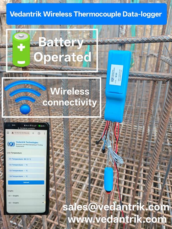
Vedantrik Wireless Thermocouple Sensors provide an advanced and reliable solution for temperature monitoring in mass concrete structures. The system is specially designed to measure the internal temperature of concrete during the hydration process, helping engineers control thermal gradients and prevent thermal cracking in large concrete elements.
Mass concrete structures such as raft foundations, pile caps, piles, dams, footings, and large foundations generate significant heat during cement hydration. If the temperature difference between the concrete core and surface becomes excessive, it may lead to thermal stress and cracking.
Using Vedantrik wireless thermocouple sensors, engineers can continuously monitor concrete temperature in real time without the complexity of long cables or external power supply.
Thermocouple Installation in Concrete
For accurate concrete temperature monitoring, thermocouple sensors are installed inside the reinforcement cage before concrete pouring.
At a typical monitoring location, 3–4 thermocouple sensors are installed at different depths when the concrete thickness is around 1.8–2.0 meters.
The sensors are generally positioned at:
Top layer of concrete
Middle or core zone
Bottom layer
Each sensor is securely fixed to the reinforcement bars using cable ties or binding wire to ensure stable positioning during concrete pouring and vibration.
Advantages of Vedantrik Wireless Thermocouple Sensors
The Vedantrik wireless monitoring system eliminates traditional wiring and simplifies temperature monitoring on construction sites.
Key advantages include
Completely Wireless Concrete Temperature Monitoring
Battery Operated Thermocouple Sensors
No Long Cable Installation Required
Quick and Easy Site Installation
Continuous Real-Time Concrete Temperature Monitoring
Suitable for Mass Concrete Structures
This system reduces installation complexity while providing accurate temperature data throughout the concrete curing period.
Concrete Temperature Monitoring Duration
Concrete temperature is typically monitored for 7 to 14 days after casting, depending on project specifications.
The collected temperature data helps engineers evaluate:
Peak hydration temperature
Core vs surface temperature difference
Thermal cracking risk in mass concrete
Concrete maturity and strength development
These measurements are critical for quality control, structural durability, and compliance with thermal control plans in infrastructure projects.
Applications
Vedantrik Wireless Thermocouple Sensors are widely used in:
Mass Concrete Temperature Monitoring
Raft Foundation Monitoring
Pile and Pile Cap Monitoring
Bridge Foundations
Dam Construction Projects
Large Industrial Foundations
Why Choose Vedantrik Wireless Thermocouple Sensors
Vedantrik offers a cost-effective, reliable, and easy-to-install concrete temperature monitoring system that helps contractors, consultants, and project engineers maintain proper thermal control in mass concrete construction.
The wireless design eliminates cable management issues, reduces installation time, and ensures continuous temperature monitoring during the most critical curing period.
Wireless thermocouple sensors
Battery operated – No external power required
No long cable runs
Real-time temperature monitoring of concrete core
Maturity & strength estimation possible
Ideal for raft foundations, piles, footings and mass concrete
Wireless Mass Concrete Temperature Monitoring & Maturity Sensor – VedaLite by Vedantrik Technologies
For Temperature controlled concrete and other concrete members.
Mass concrete elements such as rafts of High rise buildings, dams, thick foundations, piers, piles, and hot-block castings generate significant internal heat due to the exothermic hydration of cement. If this heat is not properly monitored, thermal gradients develop between the core and surface, leading to thermal stresses, micro-cracking, reduced durability, and long-term structural risks.
International standards such as ASTM C1074 (Concrete Maturity Method) explain how temperature history can be used to calculate maturity and strength development using scientific models like the Nurse–Saul and Arrhenius equations. This method allows engineers to predict real-time strength, optimize curing, and make informed decisions about formwork removal and prestressing operations.
Introducing VedaLite – Wireless Concrete Temperature & Maturity Sensor
VedaLite by Vedantrik Technologies (Mumbai, India) is an advanced wireless concrete temperature monitoring and maturity system designed for mass concrete, high-rise buildings, infrastructure, and precast applications worldwide.
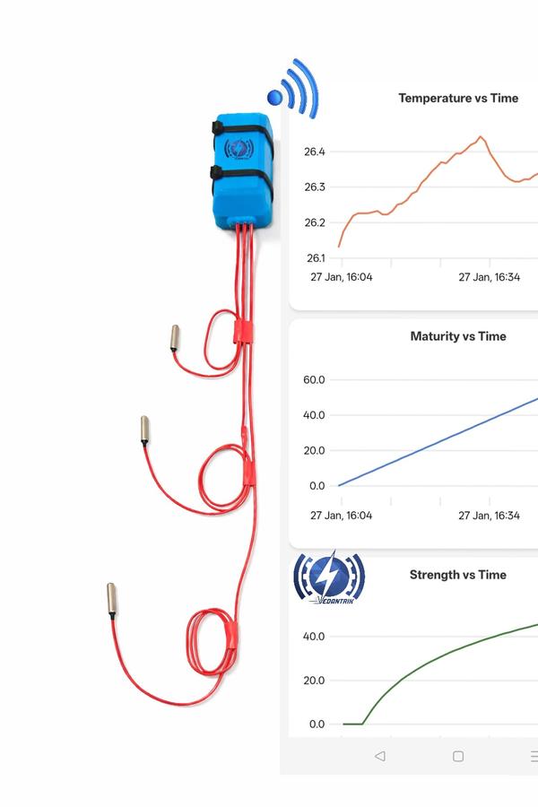
This innovative single wireless module is capable of measuring temperature at four critical locations simultaneously and also gives the Idea of thermal gradient:
- Ambient temperature
- Top of the concrete
- Middle of the concrete
- Bottom of the concrete
This multi-point sensing approach ensures accurate thermal profiling of rafts, dams, foundations, piers, piles, and thick structural elements.
Why Wireless Monitoring is Superior
Traditional wired temperature monitoring systems face multiple challenges:
- Signal errors due to long wire lengths
- Wire damage during reinforcement and concreting
- Data loss or inaccurate readings
- Complex installation and maintenance
VedaLite wireless technology eliminates these problems by:
- Removing long wire runs
- Preventing damage during casting
- Ensuring reliable, uninterrupted data
- Reducing installation time and labour costs
Economical Single-Module Multi-Point Monitoring
Unlike conventional systems that require multiple sensors and cables, VedaLite uses a single compact module to monitor four critical points.
This makes it:
- More economical
- Faster to deploy
- Easier to manage on large sites
- Ideal for high-rise rafts, dams, and infrastructure projects
Battery-Operated – No 24/7 Power Dependency
VedaLite operates on a long-lasting battery for up to 60 days, which:
- Eliminates the need for continuous power supply
- Reduces site dependency on generators
- Ensures uninterrupted monitoring even in remote locations
Real-Time Data, Memory & Graphical Analysis
The system features:
- Inbuilt memory for continuous data logging
- Temperature vs. time graphical representation
- Wireless connectivity with mobile phones and laptops
- Real-time monitoring from anywhere on site
This allows engineers to:
- Track temperature rise and fall
- Control thermal gradients
- Prevent cracking
- Make informed construction decisions
Sacrificial and Reusable System Options
Vedantrik offers flexible solutions:
- Low-cost sacrificial wirless Concrete temperature multi-point sensing modules for single-use projects (mostly prefferd as No huge investment or high upfront cost involved)
- Reusable transmitter modules where only the sensors are sacrificial and transmitter is Re-Usable with extra cost.
This provides cost-effective solutions for both large infrastructure and repetitive construction projects.
Maturity & Strength Monitoring for Structural Concrete
When used in:
- Columns
- Beams
- Slabs
- Precast elements
- In-situ structures
- PT slabs
The same module can provide:
- Concrete maturity values
- Real-time strength estimation
- Reduced dependence on cube testing
- Accurate formwork removal timing
- Safer prestressing operations
As per ASTM C1074, a maturity-strength correlation is established for the specific mix design, enabling reliable strength predictions from day one.
Applications
- High-rise raft foundations
- Mass concrete structures
- Dams and spillways
- Bridge piers and pile caps
- Deep foundations and piles
- Hot-weather concrete
- Precast plants
- PT slabs and structural elements
Why Choose Vedantrik Technologies
- Wireless, cable-free monitoring
- Economical multi-point sensing
- Up to 60-day battery operation
- Real-time mobile and laptop connectivity
- Inbuilt data memory and graphs
- Sacrificial and reusable options
- Suitable for mass and structural concrete
- Developed and deployed in major infrastructure projects
Vedantrik Technologies – Mumbai, India
Delivering advanced wireless concrete monitoring solutions for projects across India and worldwide.
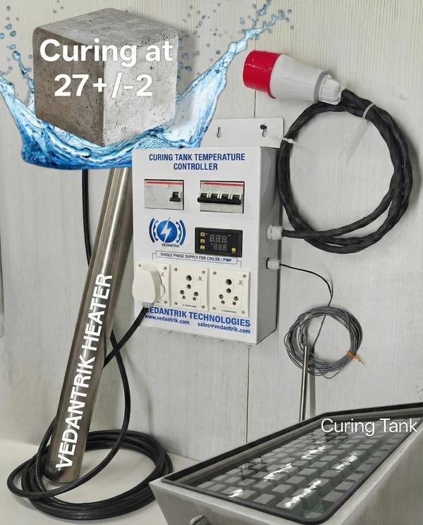
Curing Tank Temperature Controller for Concrete Cubes
NABL Calibrated | Single & Three Phase | Waterproof & Shockproof | Heater, Chiller & Pump Ready
Vedantrik Technologies presents an advanced curing tank temperature controller designed specifically for concrete cube curing tanks used in NABL-accredited laboratories, RMC plants, construction site labs, and infrastructure projects.
The system accurately maintains the standard curing temperature of 27 ± 2 °C, as prescribed by IS and NABL guidelines. Equipped with an intelligent temperature controller, SS316 waterproof immersion heaters, and built-in electrical safety protections, this solution eliminates manual temperature monitoring and ensures consistent, audit-compliant curing conditions.
Each system can be supplied with an NABL-traceable calibration certificate, making it suitable for laboratory audits and quality assurance processes.
Concrete Curing Tank Temperature Control System
This plug-and-play curing tank controller manages heating during winter and cooling during summer, ensuring uninterrupted and uniform curing of concrete test specimens.
The controller supports both single phase and three phase power supplies, allowing it to work seamlessly with different tank sizes and heater configurations without any modification.
Ideal Applications
Concrete cube curing tanks
NABL civil engineering laboratories
Construction site testing laboratories
RMC plants and QA/QC departments
Infrastructure and government projects
Technical Specifications – Curing Tank Controller
Power Supply: Single Phase / Three Phase AC, 230 V
Maximum Current Capacity: 32 Amps
Temperature Set Point: 27 ± 2 °C
Temperature Accuracy: ±1 °C
Controller Power Cord Length: 2 meters
Temperature Sensor Cable Length: 5 meters
Plug & Play Connections
Heater connection
Chiller connection
Water circulation pump connection
Temperature sensor connection
No skilled installation required.
Key Features of Curing Tank Temperature Controller
Compatible with single phase and three phase heaters
Dedicated socket for chiller (summer curing)
Dedicated socket for circulation pump
Built-in short circuit and over-current protection
Integrated MCB and RCCB for complete electrical safety
Rugged design suitable for laboratory and onsite conditions
Smart Heating & Cooling Logic (Energy Efficient)
Heating Control – Winter Operation
Heater switches OFF above 27 °C
Heater switches ON below 25 °C
Prevents overheating and reduces power consumption
Chiller Control – Summer Operation
Chiller switches ON above 29 °C
Chiller switches OFF below 25 °C
Maintains curing temperature as per NABL and IS standards
Heater Selection Based on Curing Tank Volume
Below 2000 liters: Single phase heater recommended
Above 2000 liters: Three phase heater recommended
The controller supports both heater types without any modification.
Electrical Load Capacity of Controller
Three Phase Heater Load
Heater Rating: 4 kW per unit
Minimum Load: 1 × 4 kW
Maximum Load: 4 × 4 kW (Total 16 kW)
Single Phase Heater Load
Heater Rating: Up to 2 kW per unit
Minimum Load: 1 heater
Maximum Load: 3 heaters (Total 6 kW)
Note:
Single phase heaters draw higher current; therefore, lower total power is recommended. For large curing tanks, three phase heaters provide better efficiency and stability.
SS316 Waterproof & Shockproof Immersion Heaters
Three Phase Immersion Heater
Power Rating: 4 kW
Cable Length: 5 meters
Cable Type: 5-core
Heater Material: SS316
Protection: Waterproof & shockproof
Single Phase Immersion Heater
Power Rating: 2 kW
Cable Length: 5 meters
Cable Type: 3-core
Heater Material: SS316
Protection: Waterproof & shockproof
Recommended Heater Configuration for Curing Tanks
Single Phase System (Small & Medium Tanks)
2000 liters: 1 × 2 kW heater
4000 liters: 2 × 2 kW heaters
6000 liters: 3 × 2 kW heaters
Maintains 27 ± 2 °C curing temperature.
Three Phase System (Large Tanks)
Up to 2500 liters: 1 × 4 kW heater
Up to 5000 liters: 2 × 4 kW heaters (8 kW)
Up to 7500 liters: 3 × 4 kW heaters (12 kW)
Up to 10,000 liters: 4 × 4 kW heaters (16 kW)
Best Practices for Uniform Concrete Curing
Interconnect multiple curing tanks using a water circulation pump
For identical tanks in the same environment, one temperature sensor is sufficient
For different tank sizes, place the sensor in the largest tank
Use multiple controllers for independent temperature control
Multichannel curing tank controller available for economical multi-tank operation
NABL Compliance & Custom Solutions
NABL-traceable temperature calibration certificate available
Multichannel and customized curing tank controllers
Designed for NABL labs, RMC plants, infrastructure projects, and site laboratories
Contact for Pricing & Technical Support
📞 8452062580
📧 sales@vedantrik.com
Topic covered above
Curing tank temperature controller
Concrete cube curing tank controller
NABL curing tank temperature controller
Concrete curing tank heater
SS316 immersion heater for curing tank
Single phase curing tank heater
Three phase curing tank heater
Concrete laboratory curing equipment
Curing tank temperature control system
Curing Tank Temperature Controller
product-detail-entry-exit
311, Sagar Industrial Estate, Western Express Hwy, opp. Dahisar toll Naka, Diamond Industrial Estate, Dahisar East, Mumbai, Maharashtra 400068, India


 Chat with us