Thank you for writing to us. One of our executive will reach back to you through your submitted medium. In case there’s an urgency, feel free to connect over WhatsApp for faster response.
Prefer calling? Dial +918043694111 (International callers) or 08043694111 (Indian callers).
Mass Concrete temperature Monitoring system
Mass concrete temperature monitoring device developed by Vedantrik technologies is an advanced temperature monitoring and data logging system specifically designed for mass concrete applications like raft, foundations, hot blocks and other mass concretes to prevent thermal stresses and micro cracking.
Wire-length Challenges in Mass Concrete Temperature Monitoring
In mass concrete applications, temperature sensors are typically embedded at multiple levels — the top, middle, and bottom of the pour — to accurately monitor temperature differentials during curing. However, in high-rise building foundations, the raft thickness can reach up to 3 meters or more, creating significant wire-length challenges.
As the sensors are placed deeper within the concrete, the distance between the sensors and the data loggers (which are usually installed at a controlled, accessible location) can exceed 5 meters. This extended wire-length can lead to inaccurate or higher temperature readings.
The commonly used RTD (Resistance Temperature Detector) thermocouples in concrete temperature monitoring are typically accurate only up to a cable length of approximately 5 meters. Beyond this distance, the increase in lead resistance can result in elevated or higher temperature readings. This is particularly problematic because the lead resistance is non-linear and not directly proportional to the cable length, making it difficult to apply standardised correction factors. Consequently, extended cable lengths introduce a significant source of error in temperature measurements.
But the device developed by Vedantrik technologies for mass concrete temperature monitoring can give accurate temperature readings even if wire-lengths are above 100 meters with accuracy of +/- 1 degree Celsius.
The device logs temperature data at user-defined intervals, with a standard recording interval of 30 minutes. The system utilises high accuracy sensors, which are embedded in the concrete, during casting and remain in place throughout the curing process. These sensors feed temperature data to the device’s internal storage, which can be accessed later wirelessly using mobile phone or laptop via wifi, the device supports Wi-Fi connectivity, allowing users to access and monitor data in real time through a PC, laptop, or mobile device. By providing accurate and timely temperature data, the system supports informed decisions regarding concrete strength development, enabling optimised construction schedules, timely formwork removal, and improved quality control in mass concrete applications.
Key Features:
1. Wide Temperature Sensing Range with High Accuracy
The device is equipped with high-precision sensors capable of measuring temperatures from the time of concrete casting through the entire curing period. The system accurately captures internal temperatures during the critical heat of hydration phase, providing essential data for quality control and structural safety. The sensors offer reliable performance, ensuring accurate temperature readings necessary for maturity-based strength estimation.
2. Automatic Logging with 30-Minute Interval (User-Defined Options)
The device records temperature data automatically at regular intervals, by default set to 30 minutes that can be configured to suit specific project requirements. This flexibility allows engineers to tailor the data collection frequency based on the concrete mix, ambient conditions, and structure type, optimising both storage and monitoring needs..
3. Multiple Sensor Channel Options for Mass Concrete
The device comes with 16 channels, each can be connected to a different temperature sensor, allowing temperature monitoring at several points within a single pour. This is especially beneficial in mass concrete applications, where thermal gradients and differential heating can impact structural performance and cracking risk.
4. Onboard Storage and Wireless Data Access
Temperature data is stored locally on the device and can be retrieved via memory card. In addition, this device features built-in Wi-Fi connectivity, enabling users to connect through laptops, PCs, or smartphones to view real-time data, manage sensor inputs, and download detailed reports for documentation and compliance.
Concrete temperature directly affects hydration, setting, and strength development. Concrete Temperature Monitoring Devices help engineers track temperature changes during curing, ensuring optimal conditions are maintained.
In Mumbai’s climate, with varying temperatures and humidity levels, monitoring concrete temperature becomes vital. Vedantrik Technologies provides advanced monitoring systems that record accurate data, helping project managers maintain curing consistency.
By tracking temperature variations, contractors prevent issues such as thermal cracking, improper hydration, or delayed strength gain. These devices support better decision-making and improve the long-term durability of structures.
For precision concrete temperature monitoring devices in Mumbai, trust Vedantrik Technologies and enhance the quality of your construction projects.
Concrete temperature monitoring is a critical process in ensuring the structural integrity and long term durability of large concrete placements. Mass concrete refers to large volumes of concrete that require specific measures to deal with the excessive generation of heat from hydration and change in volume associated to minimise micro-cracking due to thermal stress. In large scale projects continuous temperature monitoring becomes essential at the early stages after the placement, where thermal gradient and excessive heat can alter the development of micro-structures in concrete causing thermal cracks which are detrimental to the structural integrity of the concrete.
In the evolution of concrete from different phases, an exothermic reaction occurs between the cement and water which results in generation of heat called as heat of hydration. The amount of heat generated primarily depends on the composition of the concrete mix design. In mass concrete, this heat is not able to dissipate quickly due to low surface area- to -volume ratio, resulting in the significant increase in internal temperature, sometimes exceeding 70°C. This can become concerning because the difference in between the hot internal and cooler external surface can create a thermal gradient that can induce tensile stresses, potentially leading to thermal crack development.
Monitoring the temperature during these initial phases of development is crucial for quality control and compliance with various regulatory codes. As per the guidelines of ACI 301 and ACI 207.1R, the maximum temperature limit allowance ranges from 65°C to 70°C for internal temperatures and the difference between the ambient and internal temperature must not exceed or be less than 20°C.
For continuous temperature monitoring, temperature sensors or thermocouples are embedded at different depths and locations within the concrete. The data is logged into a temperature monitoring device which allows the engineers to take immediate necessary actions if the temperature exceeds the safe limit. In addition the maturity method, as defined in ASTM C1074, can be used in parallel with temperature monitoring to estimate in-place strength gain. Since strength development is temperature-dependent, combining maturity and temperature data offers a comprehensive view of both thermal and structural performance.
In extreme cases or during hot weather concreting, pre-cooling (cooling the materials before mixing), post-cooling (using embedded cooling pipes through which chilled water is circulated), and surface insulation are employed to manage temperature rise. These methods aim to control the rate of temperature development and limit differential temperatures between the core and surface, thereby reducing thermal stresses.
Purpose of temperature monitoring in mass concrete:
1. Monitoring ensures concrete cures within the ideal temperature range. Too cold slows hydration, delaying strength gain; too hot accelerates it, reducing final strength and durability.
2. Temperature data helps estimate how quickly concrete is gaining strength. This guides safe timing for formwork removal, loading, or post-tensioning.
3. In mass pours, temperature differences between the core and surface can cause cracking. Monitoring helps manage cooling rates to reduce this risk.
4. In low temperatures, monitoring ensures concrete doesn't freeze before setting. It supports the use of heating or insulation when needed.
5. High heat can cause rapid moisture loss and shrinkage cracks. Monitoring allows for cooling methods or mix adjustments to maintain quality.
6. Real-time temperature data supports timely decision-making, helping avoid delays while ensuring the concrete has reached required strength.
Principle of Concrete temperature monitoring:
The thermal behaviour of mass concrete is governed by the exothermic hydration reaction, low thermal diffusion, low surface area-to-mass ratio, which in conjunction can lead to thermal cracking and long-term durability impairment, if not regulated with great concern. Temperature monitoring in mass concrete, therefore, becomes the base on understanding the thermal gradient induced during the hydration process, in conjunction with thermal & structural interaction that occurs due to differential thermal strain in between internal and external zones of the concrete mass.
The primary heat generation is derived from the exothermic hydration of portland cement phases, primarily tricalcium silicate, dicalcium silicate, since their heat evolution profiles are temporally variant and sensitive to mixture proportions, ambient temperatures, and presences of cementitious materials. The volumetric heat generation within the matrix leads to progressive elevation of internal temperature, which can rise beyond 65°C to 70°C in high cement contents while the outer exposed surface dissipates heat more efficiently via conduction, convection and by radiation, resulting in formation of a thermal gradient. The resulting thermal gradient then induces differential change within the concrete mass.
Internally, the concrete goes under thermal expansion during the peak hydration, whereas the outer surface being cooler, may undergo regional contraction, this creates difference in the hardness at various points in concrete. Upon the subsequent cooling, the core begins to shrink, but the surrounding hardened shell resists this contraction, preventing the volumetric movement, thereby imparting tensile stresses in the interior zone. These internal tensile stresses can significantly lower the development of compressive strength, leading to the formation of thermal induced cracks.
The concrete's natural low diffusivity contributes to slow temperature equalisation across the cross-section, thus sustaining high temperature differentials over extended duration. Another critical aspect for temperature monitoring is the time-dependent nature of materials in concrete. Since the thermal strains are governed by both temperature changes and time-dependent mechanical properties, the process of temperature monitoring becomes essential in understanding the viscoelastic nature of the concrete. Accurate temperature data, therefore, becomes essential to capture the real-time behaviour of the concrete to predict its stress-strain response under thermal loading. Furthermore, especially in mass concrete systems incorporating additives such as fly ash, slag, or silica fumes, kinetics of the hydration often get modified, contributing to prolonged heat evolution. Temperature monitoring in such systems must account for the synergistic thermal contribution of secondary reactions. Hence, concrete temperature monitoring becomes an important tool in the process of concrete strength development throughout the curing phase.
Components of Concrete temperature monitoring
1. Temperature Sensors: Embedded in the concrete to measure internal temperatures during curing. Common types include thermocouples, and digital sensors, all designed to withstand harsh construction environments.
2. Data Loggers: Records the temperature readings from sensors at regular intervals and logs the data in internal memory.
3. Wireless connectivity: System can connect with Mobile phone laptop PC using Wifi.
Standard procedure: Overview
1. Sensor Installation
Sensors are securely positioned within the reinforcement cage or attached to the formwork at pre-identified locations. Proper spacing and orientation are ensured to prevent sensor displacement during concrete placement. All wiring is routed through protective conduits or sleeves to safeguard against mechanical damage, moisture ingress, or interference during pouring and compaction operations. The integrity of the sensor installation is verified prior to the pour.
2. Concrete Placement and Monitoring Activation
Once the concrete is placed, the monitoring system is activated. Data loggers or wireless transmitters begin recording temperature at set intervals. The initial temperature readings immediately after placement help establish baseline values for curing analysis and thermal control.
3. Real-Time or Periodic Data Collection
Depending on the monitoring system employed, temperature data is downloaded wirelessly .
4. Data Analysis and Interpretation
Engineers interpret the temperature data in accordance with project-specific thermal control plans, ACI guidelines (e.g., ACI 301 for mass concrete), or maturity method standards (e.g., ASTM C1074). Data is evaluated to ensure curing temperatures remain within acceptable limits. If deviations are identified such as excessive thermal gradients or temperature peaks, corrective measures (e.g., insulating blankets, surface cooling, delayed formwork removal) are implemented.
Result Interpretation of Concrete Temperature Monitoring
The interpretation of concrete temperature monitoring data is critical to ensuring the structural integrity, durability, and safety of a concrete element, particularly in applications involving mass concrete, cold weather concreting, or accelerated construction schedules. The data obtained from embedded sensors must be systematically analysed to assess compliance with design and curing requirements. Below are the key aspects considered during result interpretation:
1. Peak Temperature Evaluation
The maximum internal temperature recorded within the concrete mass is reviewed to ensure it remains within allowable limits, typically not exceeding 70°C (158°F) for most mixes, unless specifically engineered otherwise. Excessive peak temperatures may lead to deleterious effects such as Delayed Ettringite Formation (DEF), which can compromise long-term durability, and accelerated hydration, increasing the risk of early-age thermal cracking.
2. Temperature Differential Assessment
The temperature gradient between the core and surface of the concrete element is analysed to identify the potential for thermal cracking. A commonly accepted threshold is a differential of 20°C (36°F); however, project-specific limits may vary based on structural geometry, restraint conditions, and material properties
3. Minimum Temperature Verification
Minimum recorded temperatures are reviewed to ensure they meet the threshold for proper cement hydration, especially in cold weather concreting. Typically, concrete must be maintained above 5°C (41°F) for standard mixes, unless modified with accelerators or heated curing methods. Temperatures below this threshold may cause delayed strength development, or result in incomplete hydration , compromising final performance.
4. Time-Temperature Curve Analysis
Time-temperature curves are plotted to visualise temperature evolution over time. These curves help determine the curing trends, such as rate of temperature rise and fall,timing of exothermic peak, which typically occurs within 24–48 hours, and the rate of cooling, which should be controlled to avoid thermal stress buildup. Analysis of these curves supports engineering decisions regarding the timing of further construction operations.
5. Compliance Verification
All interpreted results are compared against the project’s thermal control plan or governing specifications (e.g., ACI 301, ACI 207.1R, CSA A23.1). Any deviations from specified temperature ranges or curing conditions must be documented, and appropriate corrective actions should be recommended and implemented.
Factors Influencing Concrete Temperature Monitoring
Several variables influence the accuracy, reliability, and interpretation of concrete temperature monitoring. Understanding these factors is essential for implementing an effective monitoring system and ensuring valid data collection during the curing process.
a. Mix Design Characteristics : The type of cement, water-to-cement ratio, use of supplementary cementitious materials (SCMs), and presence of chemical admixtures significantly affect the rate and magnitude of temperature development in concrete. High-performance or mass concrete mixes, in particular, exhibit elevated heat of hydration, which requires close thermal management.
b. Ambient and Weather Conditions : External temperature, wind, and humidity influence both the surface and internal temperatures of concrete. In cold weather, the risk of freezing during early curing stages is critical, while in hot weather, rapid surface drying or heat accumulation can lead to thermal gradients and cracking.
c. Element Size and Geometry: Larger or thicker concrete sections (e.g., footings, piers, or mat foundations) retain more heat due to lower surface-to-volume ratios, which results in slower heat dissipation and higher internal temperatures. Conversely, thin sections cool more rapidly, increasing the risk of thermal differentials.
d. Sensor Type and Quality: The accuracy and sensitivity of the sensors used (e.g., thermocouples, fiber-optic sensors, or wireless maturity sensors) influence the precision of temperature readings.
e. Sensor Placement and Depth: Improper placement of sensors can lead to unrepresentative or misleading data. Sensors must be strategically installed at different depths (core vs. surface) and locations within the structure to capture thermal gradients and localized heating. Inconsistent or shallow placement may fail to reflect internal thermal conditions.
f. Insulation and Formwork Conditions: The presence of insulation materials, thermal blankets, or sealed formwork can slow down heat loss from the concrete, affecting its thermal profile. These protective measures are especially relevant in extreme weather but must be considered when interpreting the resulting temperature curves.
Technical Specifications:
a) Temperature Sensing range: 0 °C to 100 °C
b) Temperature Accuracy: ± 1 °C
c) Number of Channels: Up to 16 channels, allowing multiple sensor connections.
d) Maximum Sensor Lead Length: more than 100 meters with accurate readings.
e) Report Generation: Automatic reports with temperature logs; download/export into your device.
f) Sensor : High-precision Temperature sensor for long-cable applications.
As a best Mass concrete temperature monitoring system Manufacturer in India we have supplied in Mumbai, Pune, Nashik, Aurangabad, Surat, Vadodara, Ahmedabad, Indore, Bhopal, Nagpur, Jaipur, Ludhiana, Ghaziabad, Delhi, Lucknow, Kanpur, Prayagraj, Patna, Ranchi, Dhanbad, Bengaluru, Hyderabad, Chennai, Coimbatore, Madurai, Visakhapatnam, Kolkata, and Srinagar.
Also we have supplied our Mass concrete temperature monitoring system including Dubai, Abu Dhabi, the United Arab Emirates, Oman, Saudi Arabia, Kuwait, and Iran. We also serve clients in Singapore, Indonesia, Thailand, and other international locations.
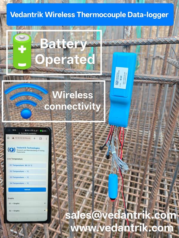
Vedantrik Wireless Thermocouple Sensors provide an advanced and reliable solution for temperature monitoring in mass concrete structures. The system is specially designed to measure the internal temperature of concrete during the hydration process, helping engineers control thermal gradients and prevent thermal cracking in large concrete elements.
Mass concrete structures such as raft foundations, pile caps, piles, dams, footings, and large foundations generate significant heat during cement hydration. If the temperature difference between the concrete core and surface becomes excessive, it may lead to thermal stress and cracking.
Using Vedantrik wireless thermocouple sensors, engineers can continuously monitor concrete temperature in real time without the complexity of long cables or external power supply.
Thermocouple Installation in Concrete
For accurate concrete temperature monitoring, thermocouple sensors are installed inside the reinforcement cage before concrete pouring.
At a typical monitoring location, 3–4 thermocouple sensors are installed at different depths when the concrete thickness is around 1.8–2.0 meters.
The sensors are generally positioned at:
Top layer of concrete
Middle or core zone
Bottom layer
Each sensor is securely fixed to the reinforcement bars using cable ties or binding wire to ensure stable positioning during concrete pouring and vibration.
Advantages of Vedantrik Wireless Thermocouple Sensors
The Vedantrik wireless monitoring system eliminates traditional wiring and simplifies temperature monitoring on construction sites.
Key advantages include
Completely Wireless Concrete Temperature Monitoring
Battery Operated Thermocouple Sensors
No Long Cable Installation Required
Quick and Easy Site Installation
Continuous Real-Time Concrete Temperature Monitoring
Suitable for Mass Concrete Structures
This system reduces installation complexity while providing accurate temperature data throughout the concrete curing period.
Concrete Temperature Monitoring Duration
Concrete temperature is typically monitored for 7 to 14 days after casting, depending on project specifications.
The collected temperature data helps engineers evaluate:
Peak hydration temperature
Core vs surface temperature difference
Thermal cracking risk in mass concrete
Concrete maturity and strength development
These measurements are critical for quality control, structural durability, and compliance with thermal control plans in infrastructure projects.
Applications
Vedantrik Wireless Thermocouple Sensors are widely used in:
Mass Concrete Temperature Monitoring
Raft Foundation Monitoring
Pile and Pile Cap Monitoring
Bridge Foundations
Dam Construction Projects
Large Industrial Foundations
Why Choose Vedantrik Wireless Thermocouple Sensors
Vedantrik offers a cost-effective, reliable, and easy-to-install concrete temperature monitoring system that helps contractors, consultants, and project engineers maintain proper thermal control in mass concrete construction.
The wireless design eliminates cable management issues, reduces installation time, and ensures continuous temperature monitoring during the most critical curing period.
Wireless thermocouple sensors
Battery operated – No external power required
No long cable runs
Real-time temperature monitoring of concrete core
Maturity & strength estimation possible
Ideal for raft foundations, piles, footings and mass concrete
Wireless Mass Concrete Temperature Monitoring & Maturity Sensor – VedaLite by Vedantrik Technologies
For Temperature controlled concrete and other concrete members.
Mass concrete elements such as rafts of High rise buildings, dams, thick foundations, piers, piles, and hot-block castings generate significant internal heat due to the exothermic hydration of cement. If this heat is not properly monitored, thermal gradients develop between the core and surface, leading to thermal stresses, micro-cracking, reduced durability, and long-term structural risks.
International standards such as ASTM C1074 (Concrete Maturity Method) explain how temperature history can be used to calculate maturity and strength development using scientific models like the Nurse–Saul and Arrhenius equations. This method allows engineers to predict real-time strength, optimize curing, and make informed decisions about formwork removal and prestressing operations.
Introducing VedaLite – Wireless Concrete Temperature & Maturity Sensor
VedaLite by Vedantrik Technologies (Mumbai, India) is an advanced wireless concrete temperature monitoring and maturity system designed for mass concrete, high-rise buildings, infrastructure, and precast applications worldwide.
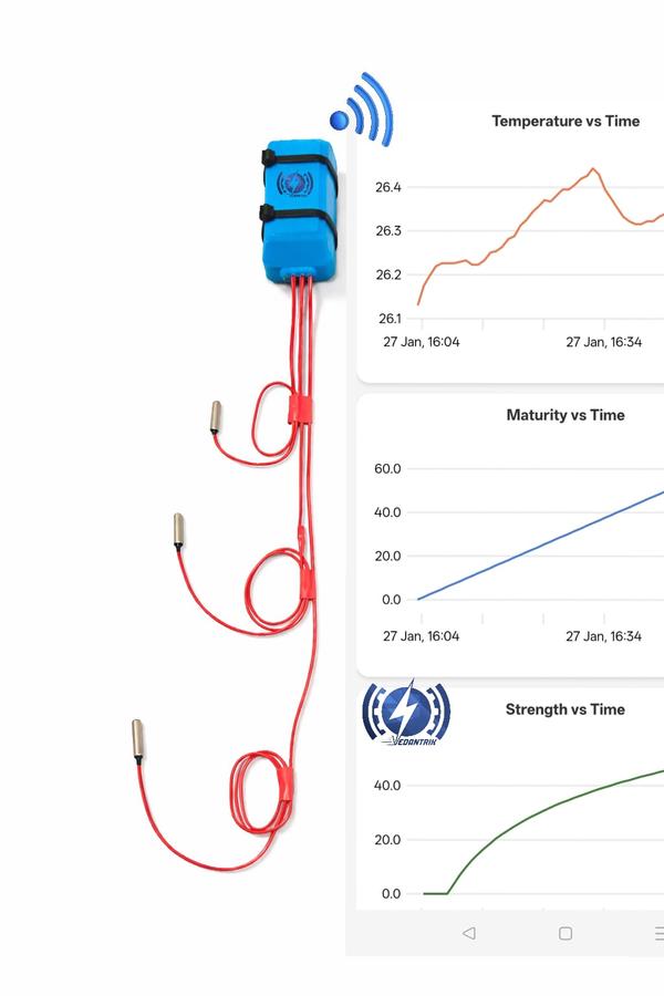
This innovative single wireless module is capable of measuring temperature at four critical locations simultaneously and also gives the Idea of thermal gradient:
- Ambient temperature
- Top of the concrete
- Middle of the concrete
- Bottom of the concrete
This multi-point sensing approach ensures accurate thermal profiling of rafts, dams, foundations, piers, piles, and thick structural elements.
Why Wireless Monitoring is Superior
Traditional wired temperature monitoring systems face multiple challenges:
- Signal errors due to long wire lengths
- Wire damage during reinforcement and concreting
- Data loss or inaccurate readings
- Complex installation and maintenance
VedaLite wireless technology eliminates these problems by:
- Removing long wire runs
- Preventing damage during casting
- Ensuring reliable, uninterrupted data
- Reducing installation time and labour costs
Economical Single-Module Multi-Point Monitoring
Unlike conventional systems that require multiple sensors and cables, VedaLite uses a single compact module to monitor four critical points.
This makes it:
- More economical
- Faster to deploy
- Easier to manage on large sites
- Ideal for high-rise rafts, dams, and infrastructure projects
Battery-Operated – No 24/7 Power Dependency
VedaLite operates on a long-lasting battery for up to 60 days, which:
- Eliminates the need for continuous power supply
- Reduces site dependency on generators
- Ensures uninterrupted monitoring even in remote locations
Real-Time Data, Memory & Graphical Analysis
The system features:
- Inbuilt memory for continuous data logging
- Temperature vs. time graphical representation
- Wireless connectivity with mobile phones and laptops
- Real-time monitoring from anywhere on site
This allows engineers to:
- Track temperature rise and fall
- Control thermal gradients
- Prevent cracking
- Make informed construction decisions
Sacrificial and Reusable System Options
Vedantrik offers flexible solutions:
- Low-cost sacrificial wirless Concrete temperature multi-point sensing modules for single-use projects (mostly prefferd as No huge investment or high upfront cost involved)
- Reusable transmitter modules where only the sensors are sacrificial and transmitter is Re-Usable with extra cost.
This provides cost-effective solutions for both large infrastructure and repetitive construction projects.
Maturity & Strength Monitoring for Structural Concrete
When used in:
- Columns
- Beams
- Slabs
- Precast elements
- In-situ structures
- PT slabs
The same module can provide:
- Concrete maturity values
- Real-time strength estimation
- Reduced dependence on cube testing
- Accurate formwork removal timing
- Safer prestressing operations
As per ASTM C1074, a maturity-strength correlation is established for the specific mix design, enabling reliable strength predictions from day one.
Applications
- High-rise raft foundations
- Mass concrete structures
- Dams and spillways
- Bridge piers and pile caps
- Deep foundations and piles
- Hot-weather concrete
- Precast plants
- PT slabs and structural elements
Why Choose Vedantrik Technologies
- Wireless, cable-free monitoring
- Economical multi-point sensing
- Up to 60-day battery operation
- Real-time mobile and laptop connectivity
- Inbuilt data memory and graphs
- Sacrificial and reusable options
- Suitable for mass and structural concrete
- Developed and deployed in major infrastructure projects
Vedantrik Technologies – Mumbai, India
Delivering advanced wireless concrete monitoring solutions for projects across India and worldwide.
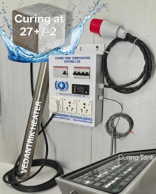
Curing Tank Temperature Controller for Concrete Cubes
NABL Calibrated | Single & Three Phase | Waterproof & Shockproof | Heater, Chiller & Pump Ready
Vedantrik Technologies presents an advanced curing tank temperature controller designed specifically for concrete cube curing tanks used in NABL-accredited laboratories, RMC plants, construction site labs, and infrastructure projects.
The system accurately maintains the standard curing temperature of 27 ± 2 °C, as prescribed by IS and NABL guidelines. Equipped with an intelligent temperature controller, SS316 waterproof immersion heaters, and built-in electrical safety protections, this solution eliminates manual temperature monitoring and ensures consistent, audit-compliant curing conditions.
Each system can be supplied with an NABL-traceable calibration certificate, making it suitable for laboratory audits and quality assurance processes.
Concrete Curing Tank Temperature Control System
This plug-and-play curing tank controller manages heating during winter and cooling during summer, ensuring uninterrupted and uniform curing of concrete test specimens.
The controller supports both single phase and three phase power supplies, allowing it to work seamlessly with different tank sizes and heater configurations without any modification.
Ideal Applications
Concrete cube curing tanks
NABL civil engineering laboratories
Construction site testing laboratories
RMC plants and QA/QC departments
Infrastructure and government projects
Technical Specifications – Curing Tank Controller
Power Supply: Single Phase / Three Phase AC, 230 V
Maximum Current Capacity: 32 Amps
Temperature Set Point: 27 ± 2 °C
Temperature Accuracy: ±1 °C
Controller Power Cord Length: 2 meters
Temperature Sensor Cable Length: 5 meters
Plug & Play Connections
Heater connection
Chiller connection
Water circulation pump connection
Temperature sensor connection
No skilled installation required.
Key Features of Curing Tank Temperature Controller
Compatible with single phase and three phase heaters
Dedicated socket for chiller (summer curing)
Dedicated socket for circulation pump
Built-in short circuit and over-current protection
Integrated MCB and RCCB for complete electrical safety
Rugged design suitable for laboratory and onsite conditions
Smart Heating & Cooling Logic (Energy Efficient)
Heating Control – Winter Operation
Heater switches OFF above 27 °C
Heater switches ON below 25 °C
Prevents overheating and reduces power consumption
Chiller Control – Summer Operation
Chiller switches ON above 29 °C
Chiller switches OFF below 25 °C
Maintains curing temperature as per NABL and IS standards
Heater Selection Based on Curing Tank Volume
Below 2000 liters: Single phase heater recommended
Above 2000 liters: Three phase heater recommended
The controller supports both heater types without any modification.
Electrical Load Capacity of Controller
Three Phase Heater Load
Heater Rating: 4 kW per unit
Minimum Load: 1 × 4 kW
Maximum Load: 4 × 4 kW (Total 16 kW)
Single Phase Heater Load
Heater Rating: Up to 2 kW per unit
Minimum Load: 1 heater
Maximum Load: 3 heaters (Total 6 kW)
Note:
Single phase heaters draw higher current; therefore, lower total power is recommended. For large curing tanks, three phase heaters provide better efficiency and stability.
SS316 Waterproof & Shockproof Immersion Heaters
Three Phase Immersion Heater
Power Rating: 4 kW
Cable Length: 5 meters
Cable Type: 5-core
Heater Material: SS316
Protection: Waterproof & shockproof
Single Phase Immersion Heater
Power Rating: 2 kW
Cable Length: 5 meters
Cable Type: 3-core
Heater Material: SS316
Protection: Waterproof & shockproof
Recommended Heater Configuration for Curing Tanks
Single Phase System (Small & Medium Tanks)
2000 liters: 1 × 2 kW heater
4000 liters: 2 × 2 kW heaters
6000 liters: 3 × 2 kW heaters
Maintains 27 ± 2 °C curing temperature.
Three Phase System (Large Tanks)
Up to 2500 liters: 1 × 4 kW heater
Up to 5000 liters: 2 × 4 kW heaters (8 kW)
Up to 7500 liters: 3 × 4 kW heaters (12 kW)
Up to 10,000 liters: 4 × 4 kW heaters (16 kW)
Best Practices for Uniform Concrete Curing
Interconnect multiple curing tanks using a water circulation pump
For identical tanks in the same environment, one temperature sensor is sufficient
For different tank sizes, place the sensor in the largest tank
Use multiple controllers for independent temperature control
Multichannel curing tank controller available for economical multi-tank operation
NABL Compliance & Custom Solutions
NABL-traceable temperature calibration certificate available
Multichannel and customized curing tank controllers
Designed for NABL labs, RMC plants, infrastructure projects, and site laboratories
Contact for Pricing & Technical Support
📞 8452062580
📧 sales@vedantrik.com
Topic covered above
Curing tank temperature controller
Concrete cube curing tank controller
NABL curing tank temperature controller
Concrete curing tank heater
SS316 immersion heater for curing tank
Single phase curing tank heater
Three phase curing tank heater
Concrete laboratory curing equipment
Curing tank temperature control system
Curing Tank Temperature Controller
product-detail-entry-exit
311, Sagar Industrial Estate, Western Express Hwy, opp. Dahisar toll Naka, Diamond Industrial Estate, Dahisar East, Mumbai, Maharashtra 400068, India


 Chat with us