Thank you for writing to us. One of our executive will reach back to you through your submitted medium. In case there’s an urgency, feel free to connect over WhatsApp for faster response.
Prefer calling? Dial +918043694111 (International callers) or 08043694111 (Indian callers).
Best Digital Rebound Hammer Hammer manufacturer in India Vedantrik Technologies,
Digital Rebound Hammer for direct Compressive strength, a quick non-destructive testing and assessment of concrete quality, uniformity, and indicative compressive strength without damaging the structure.
Benefits of Vedantrik Digital Rebound Hammer
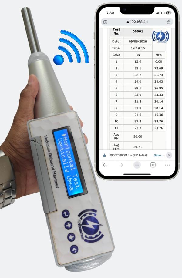
Direct Compressive strength without referring to the graph
Wireless connectivity with Laptop/PC for seamless data transfer
Automatic storage of test readings, eliminating manual data entry
Instant report generation for improved productivity
Laboratory-developed strength correlation curves for enhanced reliability
Selection of testing orientation including:
* Vertical Upward
* Vertical Downward
* Horizontal
* Inclined Upward
* Inclined Downward
Customized correction factors developed and validated by experienced engineers in the laboratory
Improved accuracy and consistency in concrete strength estimation
Digital database creation for quality control and audit traceability
Reduced testing time and enhanced operational efficiency
Engineered for Modern Concrete Testing
The intelligent software allows users to select the testing direction before measurement, automatically applying the appropriate correction factors and correlation curves. This significantly reduces human intervention and ensures more reliable strength estimation compared to conventional manual methods.
As the construction industry increasingly adopts digital technologies, testing equipment must evolve beyond manual data collection. The Vedantrik Digital Rebound Hammer represents a step forward in the digital transformation of concrete testing, quality assurance, and structural condition assessment.
Ultrasonic Pulse Velocity Meter:
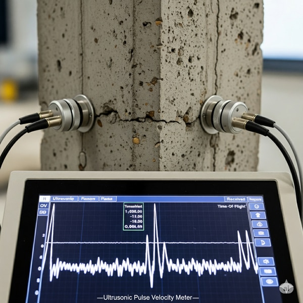
The Ultrasonic Pulse Velocity (UPV) test is a widely used non-destructive testing method for assessing the quality, integrity, homogeneity and internal conditions of the concrete. The test is fundamentally based on measuring the velocity of the ultrasonic pulse as it travels through the concrete medium. The velocity of the sound waves in concrete depends on its density, homogeneity and internal continuity, therefore , any defects such as cracks, voids, and honeycombing will affect the travel time and thus the calculated velocity.
In UPV an electroacoustical transducer produces a high frequency electrical pulse which is converted into mechanical wave (ultrasonic pulse),and this pulse propagates through the concrete and is detected by a receiver which converts it back into an electrical signal. The time of travel (t) of the pulse between the transducer and receiver is measured precisely using an electronic timer. The pulse velocity (v) is then calculated using a general formula v=l/t, and the result is expressed in kilometers per second (Km/s).
The test can be conducted in three ways; direct, semi-direct and indirect transmission depending on the site accessibility. In direct transmission the emitter and receiver are placed on opposite faces of the concrete, allowing the pulse to travel directly through the material. Since the pulse travels the shortest distance, it gives the most accurate and consistent results. In a semi-direct method the emitter and receiver are placed at right angle or adjacent surfaces, where the pulse travels diagonally through the concrete. This method is particularly used when only two adjacent surfaces are available. Finally, in the indirect method both emitter and the receiver are placed on the same surface. Although this arrangement gives lower velocity value, it is still useful for locating cracks and defects when only one side is accessible.
To ensure reliable readings, the contact surface between the transducers and the concrete must be applied with a couplant such as grease, petroleum jelly, other gel based materials to eliminate air gaps and improve the transmission of the ultrasound. Interpreting the UPV result involves comparing the calculated velocity with the standard reference values provided by IS 516 (Part 5/Sec 1): 2018 and ASTM C597. However, these values may vary depending on the mix design, aggregate type, and environmental conditions. Therefore the results of UPV must also be compared with other NDT methods , for evaluating uniformity, quality and deterioration in concrete.
Purpose of Ultrasonic pulse velocity test:
1. To evaluate the quality and uniformity of the concrete.
2. To detect internal cracks, voids, honeycombing, or deterioration
3. Can be used to estimate the strength of concrete indirectly, when correlated with a compressive strength test.
4. Assess homogeneity between different parts of a structure.
Principle of Ultrasonic pulse velocity test:
The ultrasonic pulse velocity test works on the principle of elastic wave propagation through heterogeneous solid media and its correlation with the mechanical integrity, density,and homogeneity of concrete. It exploits the behaviour of longitudinal stress waves (P-waves) that transverse the material in response to a transient mechanical excitation of ultrasonic pulse frequency, typically ranging from 20 kHz to 150 kHz. The fundamental concept is that the velocity of propagation of these waves is intrinsically governed by the mass density of the medium, which are, in turn, influenced by the material's micro-structural composition, degree of compactness, presence of micro-cracks, elasticity, and the quality of the inter-facial transition zone between the aggregate and cement paste.
In concrete, which is an inherently heterogeneous composite the relationship between composition, density and its elasticity becomes more complex due to scattering, reflection, refraction and mode of conversion effects that occur at the boundaries of different constituent phases. However, effective pulse velocity observed in concrete can still be regarded as a representative parameter of its overall stiffness and structural continuity. The propagation of ultrasonic pulses in concrete is strongly influenced by the acoustic impedance miss matches between the constituent materials. It dictates the degree of transmission and reflection of the wave at the phase boundary. When the ultrasonic pulse encounters an interface between the medium of differing impedance, part of the wave energy is reflected and the rest is transmitted. Hence, any discontinuity due to cracks, voids, or poorly bonded interface introduces additional reflection and scattering phenomena, effectively increasing the transmit time of the pulse between the two points and thereby reducing the apparent e recorded velocity. The upv therefore serves as a macroscopic indicator of the structural integrity of the concrete. The transmit time of the ultrasonic pulse depends on both the elastic property and path continuity.
In a well hydrated cement matrix, the inter-granular complexes are continuous and stiff, giving higher elastic moduli which in turn yields higher pulse velocity. In contrast, micro-cracking due to shrinkage, thermal stress, or load-induced damage disrupts this continuity, effectively reducing the effective stiffness and thus the propagation velocity. In essence, the UPV test is an application of the relationship between the wave propagation velocity, elastic nature of the concrete which is dictated by micro-structural uniformity and continuity.
Measurement of Ultrasonic Pulse Velocity test:
The test is based on measuring the time taken (T) by an ultrasonic pulse velocity to travel through a known path length (L). The pulse velocity (V) depends on the elastic properties of the concrete, and is calculated by the following formula:
V=L/T
Where,
V = Velocity of the pulse (m/s or km/s)
L = Path length between the two Transducers (emitter and receiver)
T = Transit time of the pulse (s)
Components of Ultrasonic Pulse velocity test:
The main components of an Ultrasonic Pulse Velocity testing system are:
1. Main Unit (UPV Tester): This is the central device that controls the entire test. It generates electrical pulses, measures the transit time of ultrasonic waves, and displays or records the pulse velocity. It also supplies power to the transducers and processes the received signals.
Transducers (Transmitter and Receiver): The transmitter converts electrical pulses into ultrasonic waves, and the receiver converts the returning waves back into electrical signals.
2. Couplant: A gel, grease, or paste applied between the transducers and the concrete surface to ensure proper transmission of ultrasonic waves by removing air gaps.
3. Connecting Cables: Connect the transducers to the main unit, allowing transmission and reception of electrical signals.
Standard Procedure for Ultrasonic Pulse Velocity (UPV) Test
The Ultrasonic Pulse Velocity (UPV) test is carried out according to IS 516 (Part 5/Sec 1): 2018 or ASTM C597 to determine the quality, uniformity, and integrity of concrete. The following steps outline the standard testing procedure:
1. Application of Couplant on the surface
A thin layer of Couplant, such as petroleum jelly, grease, or gel, is applied to the contact area between the transducers and the concrete surface. The Couplant eliminates air gaps and improves the transmission of ultrasonic pulse from the transducer into the concrete, ensuring more accurate reading.
2. Positioning of the transducer
The transmitting and receiving transducers are positioned on the concrete using one of three arrangements depending on accessibility. In direct transmission the transducers (emitters and Receivers) are placed opposite faces of the concrete specimen, it is considered the most accurate method. In Semi-Direct transmission the transducers are placed on adjacent faces, while in indirect (Surface) transmission both transducers are placed on the same face (least accurate but useful when only one face is accessible). Proper alignment of the transducers ensures accurate measurement of pulse travel time.
3. Measurement of the Path length
The distance between the center of the two transducers is measured carefully using a measuring tape or scale. This measured distance represents the path length (L) through which the ultrasonic pulse travels.
4. Recording the transit time
The main unit of the UPV is switched on to generate an ultrasonic pulse through the transmitter. The pulse travels through the concrete and is received by the receiver. The time taken by the pulse to travel this distance, known as the transit time (T), is displayed on the device. Multiple readings are taken at each point, and the average value is used for accuracy.
Result interpretation of Ultrasonic pulse velocity test:
The velocity of ultrasonic pulses through concrete depends on its density and elastic properties. The quality of concrete can therefore be classified as follows (as per IS 516 (Part 5/Sec 1): 2018 and ASTM C597):
The quality of concrete can be assessed using Pulse Velocity measurements in kilometers per second (km/s). Concrete with a pulse velocity >4.40 km/s is considered Excellent, indicating very good quality, dense, and uniform concrete. Pulse velocities in the range of 3.75 to 4.40 km/s correspond to Good concrete, which is of good quality with negligible voids or cracks. When the pulse velocity falls between 3.0 and 3.75 km/s, the concrete is rated as Medium, meaning it is of fair quality and may contain minor defects or variations. Concrete with a pulse velocity < 3.0 km/s is considered Doubtful, as it is likely weak, porous, or damaged.
Factors Influencing Ultrasonic Pulse Velocity (UPV) Test
Several factors can affect the accuracy and reliability of the UPV test results. These factors influence the speed at which ultrasonic waves travel through concrete:
1. Moisture content in the specimen:
Concrete that has higher moisture content allows ultrasonic pulses to travel faster because water fills the pores, improving transmission. Whereas, dry concrete generally gives lower pulse velocity readings
2. Path length and Geometry:
Very short path length or irregularly shaped specimens can lead to measurement inaccuracies, as the pulse may not travel uniformly through the material.
3. Concrete Mix and Density:
Denser and more homogeneous concrete provides higher velocities, while concrete with voids, honeycombing, or poor compaction show lower velocities
4. Surface condition and Couplant application:
Rough or uneven surfaces can cause poor contact between the transducers and the concrete. Hence, proper application of couplant is essential to ensure accurate readings.
Sources of Errors in Ultrasonic Pulse Velocity (UPV) Test
1. Poor surface contact:
Inadequate use of couplant or rough surface can lead to air gaps between the transducer and concrete, increasing signal loss and measurement errors.
2. Incorrect path length measurement:
Errors in measuring the distance between transducers directly affect the calculated pulse velocity.
3. Equipment calibration errors:
If the UPV testing device is not properly calibrated, the recorded transit times may be inaccurate.
4. Improper transducer placement:
Misalignment or unstable positioning of transducers can cause inconsistent readings.
5. Electrical or signal interference:
External vibrations, electrical noise, or poor signal connections can distort the received signal and lead to faulty timing measurements.
The Ultrasonic Pulse velocity Meter by Vedantrik technologies is a non-destructive testing (NDT) instrument designed to evaluate the quality, uniformity and integrity of concrete. It works by sending the ultrasonic pulses through the concrete via transmitting transducers, the pulses travelling through the material are then detected by receiving transducers on the opposite or adjacent surface. The device measures the transit time of pulses, and displays the values on the digital screen. Using the path length between the transducer, the velocity of the pulses can be calculated, which directly reflects the homogeneity, and presence of defects such as voids, cracks and honeycombs in the concrete. Designed for field and laboratory use, the device is portable and capable of testing path length up to 3 meters. To further enhance the measurement reliability, it includes a burst mode feature, which averages multiple ultrasonic pulses to provide stable readings, and a freeze function, that locks the reading on the display for convenience during the testing. Additionally, the android mobile applications enable indirect-mode calculations, streamlining workflow for engineers and quality control personnel. Lightweight, portable, and robust with a plastic housing, the Vedantrik UPV meter combines modern features with practical usability, making it a versatile and cost-effective solution for structural health monitoring, concrete quality assessment, and non-destructive evaluation of construction elements.
Key features:
1. Burst Mode for Stable Readings
In Burst Mode, the device transmits multiple ultrasonic pulses over 5–6 seconds and automatically averages the readings. This process minimises fluctuations and ensures accurate, consistent results every time.
2. Reading Hold (Freeze Function)
The instrument automatically freezes the reading on display even after the transducers are removed, allowing ample time for users to record or review data without losing results.
3. Android App Connectivity
Comes with a dedicated Android application for easy indirect mode velocity calculation and graph plotting as per IS 516 standards. The app provides a user-friendly interface for data analysis, reporting, and sharing test results on the go.
4. High Storage Capacity
Designed with a built-in record and storage facility for up to 1,000 readings, ensuring convenient data logging during large-scale testing operations or multiple project sites.
5. Long Operational Backup
Powered by an in-built rechargeable battery, the device delivers extended operational backup, ensuring uninterrupted performance even in field conditions where power availability is limited.
6. Lightweight and Compact Design
Housed in a durable ABS plastic enclosure, the unit is lightweight, compact, and easy to handle, making it ideal for both laboratory and on-site testing applications.
Technical Specifications:
a) Measurable path length: 3-4 meters in good quality concrete.
b) Time measurement range: 0.1-9999.9 μs.
c) Measurement parameters: Time and Velocity.
d) Time base:- 10MHz Quartz.
e) Frequency of Transducer: Standard 54KHz (Nominal).
f) User interface: OLED Display, keypad and PC interface.
g) PC Interface: Measurement log download.
h) Operator Adjustment: Calibrating using Calibration rod.
i) Battery Operating capacity: 8 Hrs. maximum.
j)Operating Temperature range: 0-50 degreeC.
k) Size: W-180mm x H-55mm x D-240mm.
l) Weight: 1.90 Kg
As a best Ultrasonic Pulse Velocity Meter Manufacturer in India we have supplied in Mumbai, Pune, Nashik, Aurangabad, Surat, Vadodara, Ahmedabad, Indore, Bhopal, Nagpur, Jaipur, Ludhiana, Ghaziabad, Delhi, Lucknow, Kanpur, Prayagraj, Patna, Ranchi, Dhanbad, Bengaluru, Hyderabad, Chennai, Coimbatore, Madurai, Visakhapatnam, Kolkata, and Srinagar.
Also we have supplied a range of products in Dubai, Abu Dhabi, the United Arab Emirates, Oman, Saudi Arabia, Kuwait, and Iran. We also serve clients in Singapore, Indonesia, Thailand, and other international locations.
Calibration Rod for UPV:
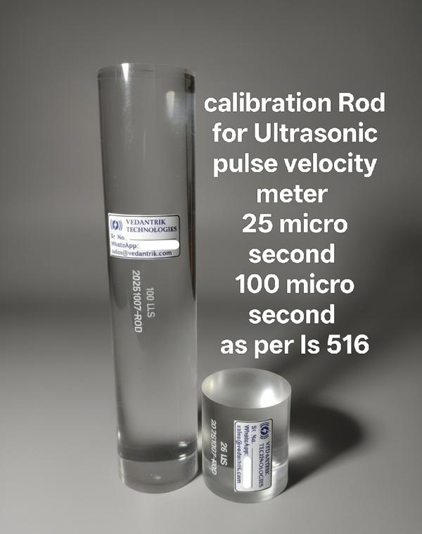
Calibration rods used in the Ultrasonic Pulse Velocity (UPV) test is a crucial tool to ensure that the readings obtained from concrete specimens are accurate and reliable. According to IS 516 (Part 5/Sec 1): 2018, the calibration of the UPV apparatus is performed using standard calibration rods of known lengths and material properties. These rods are made of a homogeneous, dense, and isotropic material, whose Ultrasonic pulse velocity values are well established. The calibration process generally involves the use of two standard rods, where the first rod labeled 25 μs, is used for initial calibration of the equipment. The second rod labeled 100 μs is then used to verify the accuracy of calibration. By checking the transit time through this 100 μs rod, engineers can confirm whether the equipment remains correctly calibrated across a wider range of travel time.
During calibration, the transmitting and receiving transducers are placed at the two ends of the calibration rod using a coupling medium such as grease or petroleum jelly to remove any air pockets that may tamper with the actual results and to also ensure good acoustic contact. A pulse is then transmitted through the rod, and the transit time is recorded, this mode of operation is called through transmission mode. Furthermore, the time measurement is then verified with reference time labeled on the rods to confirm the calibration.
This dual-rod system (25 μs and 100 μs) ensures that the UPV equipment is not only initially calibrated but also verified for linearity and consistency over different travel times. It confirms that the instrument’s internal timing circuit and transducers function correctly across the expected range of measurements. As per IS 516 (Part 5/Sec 1): 2018, such calibration and verification must be performed before and after each series of tests, or whenever there is any suspicion of instrument drift or malfunction.
Purpose of Calibration Rod:
a) To ensure measurement reliability – Calibration rods ensure that subsequent UPV readings on concrete are valid and dependable.
b) To check equipment accuracy – Ensures the UPV apparatus gives correct time readings before testing concrete.
c) To detect instrument errors – Identifies any malfunction or timing error in the transducers or electronic timer.
Principle behind Calibration:
The use of calibration rods in UPV testing is fundamentally based on the principle of elastic wave propagation through homogeneous and isotropic media. The calibration rod serves as an excellent reference medium, having well characterized elastic and geometric properties, which allows for consistent verification of accurate time measurement capability of the UPV instrument. They behave like an idealized medium for propagation, with minimal internal scattering, negligible attenuation, and uniform acoustic impedance. When an ultrasonic pulse is transmitted through the rod, the longitudinal wave propagates along a predictable path, and the received signal exhibits well-defined wavefront characteristics. Since the UPV technique determines the pulse velocity V from the ratio of the known path length L to the measured transit time T (i.e., V=L/T), the accuracy of velocity calculation critically depends on the precision of time measurement and the stability of the transducer–instrument system. Any systematic deviation in the time registration or transducer response will introduce errors in the final velocity calculation, which can lead to misinterpretation of concrete quality and durability. Therefore, the calibration rod provides a standard benchmark against which such instrumental deviations can be identified and corrected.
Components:
a) Reference Rod (25 μs): Used to establish a standard calibration range for the accuracy of time measurement in the UPV apparatus.
b) Reference Rod (100 μs): Utilised to confirm the validity and consistency of calibration across a longer propagation path length.
Standard Procedure: Overview
1) Inspect the UPV instrument, ensuring all components are functional. Select clean reference bars, typically short (25 µs) and long (100 µs), free of surface defects.
2) Apply an appropriate coupling agent (e.g., petroleum jelly or glycerol paste) to the transducer faces and bar surfaces to ensure efficient ultrasonic energy transfer and prevent signal distortion.
3) Place the transducers on the short reference bar and measure the transit time. Compare with the known value (25 µs); any deviation beyond ±0.5% indicates the need for adjustment.
4) Repeat the measurement on the long reference bar (100 µs) to confirm linearity and consistency across longer path lengths.
5) If both measurements fall within tolerances, the instrument is calibrated and ready for field testing. Any discrepancies must be corrected before concrete testing.
Factors influencing the Calibration Process:
1) Instrument Accuracy and Stability: The electronic timing system, pulse transmitter and the receiver must be stable and precise. Any drift or noise in the electronics can affect the measured transit time,leading to calibration error.
2) Transducer performance: Variation in transducer sensitivity, frequency , or wear can influence pulse generation and reception, affecting the measured time. Calibration ensures these effects are accounted for.
3) Coupling Quality: The efficiency of energy transfer between transducer and calibration rod and uniformity of the coupling agent. Poor coupling can reduce signal amplitude or introduce timing errors.
4) Transducer Alignment and Pressure: Misalignment or inconsistent contact pressure can change the effective path of the pulse, introducing errors in timing measurement during calibration.
Accurate calibration is the foundation for every reliable Ultrasonic Pulse Velocity test. Even minor errors in time measurement can lead to inaccurate interpretation of the concrete’s quality. Therefore, to ensure precision and repeatability, calibration must be carried out using a standard reference. Vedantrik Technologies provide high quality calibration rods, made from Poly-methyl Methacrylate, which behaves as an excellent medium, providing acoustic stability, homogeneity, with minimal internal scattering, negligible attenuation, and isotropic properties. These calibration rods are available in two standard configurations: a short rod (25 µs) for calibration and a long rod (100 µs) for verification and validating timing consistency over extended paths. By acting as trusted standard reference, Vedantrik Calibration rods help eliminate measurement error that may otherwise compromise the true results.For efficient and reliable UPV calibration rods in Mumbai, contact Vedantrik Technologies and ensure the highest standards of concrete quality.
As a best Ultrasonic pulse velocity Meter calibration rod Manufacturer in India we have supplied in Mumbai, Pune, Nashik, Aurangabad, Surat, Vadodara, Ahmedabad, Indore, Bhopal, Nagpur, Jaipur, Ludhiana, Ghaziabad, Delhi, Lucknow, Kanpur, Prayagraj, Patna, Ranchi, Dhanbad, Bengaluru, Hyderabad, Chennai, Coimbatore, Madurai, Visakhapatnam, Kolkata, and Srinagar.
Also we have supplied a range of products in Dubai, Abu Dhabi, the United Arab Emirates, Oman, Saudi Arabia, Kuwait, and Iran. We also serve clients in Singapore, Indonesia, Thailand, and other international locations.
Rapid Migration Penetration Test (RCMT)
When it comes to assessing the durability of reinforced concrete, the Rapid Chloride Migration Test (RCMT) has become a preferred method across engineering projects. Unlike RCPT, which measures electrical charge passing through concrete, RCMT evaluates chloride migration under an applied electric field. This approach provides faster and more reliable results, making it a valuable tool for both research laboratories and quality control departments.
Rapid chloride migration test (RCMT) is a test performed for determination of the chloride migration Coefficient in concrete, mortar or cement-based repair Materials from non steady-state migration experiments.
A concrete core of 100 mm diameter and 50 mm thickness is placed inside a rubber sleeve, which separates two compartments, one side is filled with sodium chloride (NaCl) solution (connected to the anode) and the other with sodium hydroxide (NaOH) solution (connected to the cathode). The sample is placed such that the bottom is in contact with the NaCl solution, and the top is in contact with the NaOH solution. An initial voltage of 30V is applied, and the initial current is recorded. Based on this value the RCMT apparatus recommends the next voltage and test duration as per NT BUILD 492. At the end of the test, the final temperature of the system is logged. The concrete sample is then split, and the internal surface is sprayed with silver nitrate.
This reacts with the chloride ions to form a white precipitate, marking the depth of chloride penetration. This depth is used to calculate the chloride migration coefficient, which helps determine the concrete’s ability to resist chloride-induced corrosion.
Purpose of RCMT in Concrete testing:
The results are crucial for:
1. Assessing concrete’s ability to resist migration of chloride ions, which is critical for concrete durability.
2. Assessing the long-term durability and predicting the service life of concrete structures, especially in environments with high chloride exposure, like coastal regions.
3. Provides a standardised method to evaluate concrete’s transport properties, making it useful for both research and construction application.
4. Evaluating and ensuring the quality of concrete mixes during construction.
5. Studying the effectiveness of different concrete mix designs and admixtures.
6. Quality control tool for comparing different mix designs in terms of durability.
7. Helps in optimising concrete mix for structures exposed to aggressive environments.
Principle of RCMT:
The Rapid Chloride Migration Test (RCMT), developed under Nordic Concrete Research Framework and standardised as NT BUILD 492, is an electrochemical cell test design conducted to determine the chloride ion migration coefficient of the concrete. The main principle behind this test is the establishment of external applied voltage potential across the specimen which causes the migration of chloride ions through the saturated pore structure of the concrete, which is directly associated with its durability performance in log-term, specially in relation to the chloride induced corrosion of the embedded steel reinforcements (Rebar).
The electrical potential induces a non- steady state migration condition, where the chloride ion transport is primarily by the migration rate rather than concentration driven steady state diffusion.
The test is conducted for a fixed duration typically ranging from 6 to 96 hours. After the test completion the specimen is axially slit, and the internal surface is sprayed by 0.1 M silver nitrate (AgNO3) solution. The silver nitrate reacts with the chloride ions to form silver chloride (AgCl) which appears as a white precipitate marking the penetration depth of chloride. This depth is measured at multiple radial points to calculate the average penetration depth (Xd). The average penetration depth obtained is used in conjunction with other parameters such as applied voltage, initial current, initial and final temperature, and test duration to calculate the non-steady state chloride migration coefficient (Dnssm) as per NT BUILD 492.
The test assumes negligible ion interaction and linear electric potential drop across the specimen. However, other ions may participate in charge transport, although differences in their mobility add negligible interference as the chloride determination is due to selective precipitation reaction between chloride and AgNO3.
This way the RCMT provides a quantifiable and reproducible measurement of chloride ion migration, serving as method for performance based evaluation of different concrete mixes, especially those incorporating supplementary cement materials (SCMs), chemical admixture, or concrete specimens subjected to different curing conditions. The derived migration coefficient serves as an indicator for concrete’s long-term chloride diffusion behaviour to predict durability of concrete over decades.
Measurement of RCMT:
The final calculation combines the average penetration depth with other parameters such as applied voltage, initial current, initial and final temperature, and test duration to calculate the non-steady state chloride migration coefficient (Dnssm) as per NT BUILD 492.
The formula to calculate the non-steady state migration coefficient (as per NT BUILD 492) is given below.
Dnssm = (0.0239 ∗ (273 + T) ∗ L/ (U−2)t) * (xd −0.0238 ∗ √(273 + T)∗ L∗ Xd / √U−2 )
Where:
Dnssm: non-steady-state migration coefficient, m2/s;
z: absolute value of ion valence, for chloride, z = 1;
F: Faraday constant, F = 9.648 ×10⁴ J/(V·mol);
U: absolute value of the applied voltage, V;
R: gas constant, R = 8.314 J/(K·mol);
T: average value of the initial and final temperatures in the anolyte solution, K;
L: thickness of the specimen, m;
Xd: average value of the penetration depths, m;
t: test duration in hours
Components of RCMT:
1. Vacuum desiccator and pump: For vacuum saturation of the specimen (<50 mm of Hg).
2. RCMT test Chamber: Holds the concrete specimen and creates chambers for NaCl and NaOH solutions.
3. Concrete Specimen: The sample to be tested for chloride ion permeability. Cylindrical core of standard dimension 100 mm diameter and 50 mm thickness.
4. 10% Sodium Chloride (NaCl) Solution: Placed in the chamber; source of chloride ions.
5. 0.3 N Sodium Hydroxide (NaOH) Solution: Placed to above specimen in sleeve; completes the electrical circuit.
6. Silver nitrate, AgNO₃: Used to spray split specimen surface for chloride penetration detection.
7. Silicone rubber sleeve: Covers specimen sides; inner/outer diameter.
8. Stainless steel clamp: Secures sleeve and specimen, prevents leakage.
9. Electrodes: Transfer electrical current into the solutions.
10. Power Supply (DC Voltage Source): Provides constant 0-60V across the specimen during the test.
11. Temperature sensor/ thermocouples: To monitor temperature, accuracy ±1 °C.
12. Ammeter (Current Meter): Measures the current passing through the specimen to calculate charge passed.
13. Data Acquisition system: Records current over time to compute total charge passed (in coulombs).
Standard procedure: Overview (as per NT BUILD 492)
1. Sample Preparation
Concrete specimens are prepared by cutting or coring cylindrical samples of 100 mm diameter and 50 mm thickness (±2 mm). These are typically taken from cast cubes, cylinders, or field cores. The side surfaces are sealed using rubber sleeves, epoxy, or similar material to ensure that chloride can only enter the concrete from the exposed circular faces. Specimens should be cured for a minimum of 28 days, and surface carbonation or contamination should be removed before testing.
2. Preconditioning / Saturation
To ensure accurate and repeatable results, the specimen must be fully saturated. This is done using a vacuum saturation method where the specimens are placed in a container filled with saturated calcium hydroxide [Ca(OH)₂] solution. A vacuum (≤ 50 mm of Hg) is applied for 3 hours to remove air from the concrete pores. After the vacuum is released, the specimens remain submerged in the solution for an additional 18 ± 2 hours. This step ensures the pore system is completely filled with liquid, simulating worst-case chloride ingress conditions.
3. Test Assembly
The saturated specimen is mounted in a migration cell, with its ends exposed to two different solutions, Cathode chamber (negative side) is filled with 10% NaCl (sodium chloride) solution. The Anode chamber (positive side) is filled with 0.3 N NaOH (sodium hydroxide) solution. Each chamber contains a stainless steel electrode (plate or mesh), and the entire setup is sealed to prevent leakage. The arrangement ensures unidirectional ion movement through the concrete.
4. Applying the Electric Field
Initially 30 volts DC is applied across the specimen using an external power supply. The test duration ranges from 6 to 96 hours, depending on initial current value. The electric field forces chloride ions to migrate from the catholyte (NaCl) into the concrete. During the test, the initial current, temperature, and voltage are recorded.
5. Splitting and Chloride Detection
After the test completion, the specimen is removed and split axially to expose the internal surface. The freshly split face is sprayed with 0.1 M silver nitrate (AgNO₃) solution. This reacts with any chlorides present, forming a white precipitate of silver chloride, clearly showing the depth of chloride penetration.
6. Measurement of Chloride Migration
Using a scale, the depth of the white chloride front is measured at ten evenly spaced points across the diameter of the specimen. The average penetration depth (Xd) is calculated from these readings, which serves as a basis for computing the chloride migration coefficient.
7. Calculation of Migration Coefficient
The chloride migration coefficient (Dnssm) is calculated using a standard equation provided in NT BUILD 492. The formula uses inputs such as the average penetration depth, test voltage, duration, specimen thickness, and temperature. This coefficient quantifies the rate of chloride migration under test conditions and serves as a key indicator of concrete durability.
Result Interpretation of RCMT:
The main results of the RCMT is the chloride migration coefficient (Dnssm), which is expressed in:
x * 10-12 m2/s
Lower values represent better resistance to chloride penetration, which corresponds to higher durability.
While NT BUILD 492 provides the procedure and the formula for calculating the non-steady state chloride migration coefficient (Dnssm), it does not define specific limits for durability classification. Therefore, the interpretation of the results must be done by referring to relevant research literature or guidelines provided by other institutions.
Factors influencing RCMT results:
1. Influence of Moisture Content: The test results are highly affected by the moisture content, and may lead to current fluctuations ultimately skewing the final results of the test.
2. Effect of Admixtures: Use of chemical or supplementary cementitious materials (SCMs) like silica fume, fly ash may reduce the pore size of the concrete sample, increasing the resistance to movement of chloride ion.
3. Pore structure and connectivity: The size , distribution, and inter connectivity of pores determine how easily chloride ions can move through the concrete.
4. Temperature effect: Rise in temperature increases the diffusion rate of the chloride ions, leading to higher measured migration of the chloride ions. It also affects the micro-structures in the concrete changing the final result, leading to false interpretation.
Rapid Chloride Migration Test (RCMT) Apparatus by Vedantrik Technologies
Durability of concrete depends on its resistance to chloride ingress, and the Rapid Chloride Migration Test (RCMT) is one of the most effective methods to measure it. Unlike traditional long-duration permeability tests, RCMT delivers quicker results by monitoring the migration of chloride ions under an applied electric field. This makes it a practical choice for both research laboratories and on-site quality control.
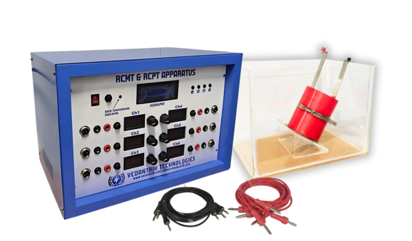
Rapid chloride migration test (RCMT) apparatus by Vedantrik Technologies is laboratory device specially made for determination of the chloride migration Coefficient in concrete, mortar or cement- based repair Materials from non-steady-state migration experiments. A concrete core of 100 mm diameter and 50 mm thickness is placed inside a rubber sleeve, which separates two compartments, one side is filled with sodium chloride (NaCl) solution (connected to the anode) and the other with sodium hydroxide (NaOH) solution (connected to the cathode). The sample is placed such that the bottom is in contact with the NaCl solution, and the top is in contact with the NaOH solution. An initial voltage of 30V is applied, and the initial current is recorded. Based on this value the RCMT apparatus automatically recommends the next voltage and test duration as per NT BUILD 492
At the end of the test, the machine logs the final temperature of the system. The concrete sample is then split, and the internal surface is sprayed with silver nitrate. This reacts with the chloride ions to form a white precipitate, marking the depth of chloride penetration. This depth is used to calculate the chloride migration coefficient, which helps determine the concrete’s ability to resist chloride-induced corrosion. The RCMT machine is available in different channel options—3, 4, 6, 8, or 12—to allow multiple samples to be tested simultaneously.
Key Features of Vedantrik RCPT Apparatus
1. Protection against power cut: Any power interruption during the test can affect the results. However, Vedantrik RCMT is equipped with an intelligent power recovery system that automatically tracks the progress and resumes the test from the exact point of interruption.
2. Automated voltage & test duration recommendation: Based on the initial current value the Vedantrick RCMT automatically calculates and recommends the next voltage along with total test duration.
3. Automatic final temperature capture: In RCMT both the initial and final temperature are required in the final calculation. To simplify the process Vedantrik RCMT apparatus automatically logs the final temperature value at the conclusion of each test.
4. In-built voltage stabiliser: Vedantrik RCMT features an advanced micro-controller based power electronics for precise voltage regulation.
5. Uninterrupted wireless connectivity: Vedantrik RCPT equipment features wireless connectivity, typically via in-built Hot-Spot, which allows for remote data access.
6. Multi-device compatibility: Vedantrik RCPT wireless feature is compatible with a range of devices, including PCs, laptops, Android mobile phones, and iPhones, ensuring that users can access and share data regardless of their operating system.
7. Protection: Vedantrik RCPT apparatus provides short circuit and over current over voltage protection.
8. Web-based software: Vedantrik RCMT comes with powerful web-based software that can be accessed by connecting via Hot-Spot with a range of devices, including PCs, laptops, Android mobile phones, and iPhones to access the data in real time.
9. In-built data acquisition system: Vedantrik RCMT features in-built data acquisition system that captures and stores all the test data, without the need for internet connection.
In Mumbai’s construction industry, where large-scale infrastructure projects require high standards of durability, RCMT helps ensure concrete can withstand aggressive environments. At Vedantrik Technologies, advanced RCMT testing equipment is developed to support engineers in achieving accurate results that comply with global standards. With user-friendly interfaces, precise control systems, and dependable output, their instruments have become a trusted choice for builders and testing labs.
RCMT plays a vital role in evaluating how effectively supplementary cementitious materials and admixtures improve resistance to chloride penetration. By integrating RCMT in routine quality checks, engineers can make informed decisions about mix design, durability enhancement, and long-term cost savings.
For reliable RCMT equipment in Mumbai, partner with Vedantrik Technologies. Get in touch today to explore solutions that ensure your concrete structures remain strong and corrosion-resistant for decades.
Technical Specifications:
a) Voltage: 0-80V DC ± 0.1V
b) Current measurement accuracy: ± 1mA
c) Tank suitable for NaCl and NaOH to conduct RCMT as per NT Build 492.
d) Ambient Temperature: 20-25°C.
e) Temperature sensing with individual sensor slot accuracy ± 1°C.
f) Input Voltage: 230V-265V.
As a best RCMT Rapid Chloride Migration test system Manufacturer in India we have supplied in Mumbai, Pune, Nashik, Aurangabad, Surat, Vadodara, Ahmedabad, Indore, Bhopal, Nagpur, Jaipur, Ludhiana, Ghaziabad, Delhi, Lucknow, Kanpur, Prayagraj, Patna, Ranchi, Dhanbad, Bengaluru, Hyderabad, Chennai, Coimbatore, Madurai, Visakhapatnam, Kolkata, and Srinagar.
Also we have supplied our RCMT Rapid Chloride Migration Test system including Dubai, Abu Dhabi, the United Arab Emirates, Oman, Saudi Arabia, Kuwait, and Iran. We also serve clients in Singapore, Indonesia, Thailand, and other international locations.
About Half cell potential test:
The half cell potential test is a widely utilised, non-destructive electrochemical technique used primarily for assessing the likelihood of the corrosion activity in steel reinforcement. It is especially designed to evaluate the electrochemical potential of steel reinforcement embedded in concrete by comparing it to the reference electrode placed on the surface. The test serves as an indirect method of estimating the corrosion activity, without physically damaging the structure or extracting reinforcing bar (rebar).
When the steel corrodes in concrete, it undergoes oxidation reaction, releasing electrons. These electrochemical processes generate a measurable potential difference between the embedded steel and the reference electrode. In a half cell test, a high impedance voltmeter is used to measure this potential difference , which reflects the electrochemical state of the steel. The reference electrode, typically a copper/copper sulfate (Cu/CuSO4) or a silver/silver chloride (Ag/AgCl), provides a stable known potential against which the steel’s potential can be compared. The steel reinforcement, if corroding, will show negative potential due to the anodic reactions taking place on its surface.
For analysis of the obtained value it becomes necessary to understand the significance of the measured potential. According to the standards like ASTM C876, a potential value measurement that is more negative than -350 mV generally indicates high probability of corrosion activity occurring at the time of measurement. It is important to note that the test only reflects the potential of corrosion at the time of testing and does not quantify the rate and the extent of corrosion damage. Several factors can influence the test accuracy and its interpretation. Moisture content plays an important role, as higher moisture content naturally increases the ionic conductivity of the concrete. Surface conditions, such as coatings or contaminants can affect electrical conductance or measurement accuracy.
Purpose of half cell potential test:
1. To detect whether corrosion activity of the steel reinforcement is actively occurring.
2. To assess the probability of corrosion in the steel reinforcement.
3. To locate corrosion prone areas across the concrete surface
4. Monitor the effectiveness of protection measures.
Principle of half cell potential test:
The half-cell potential test is based on the principle that the steel reinforcement embedded within the concrete matrix behaves as an electrochemical phase capable of participating in redox processes at the steel-concrete-pore solution interface. When a metallic electrode such as reinforced steel is immersed in a conductive medium an equilibrium is established between the metallic iron phase and its ionic species (Fe2+, Fe3+) present in the adjacent pore solution. This equilibrium gives rise to measurable potential difference, referred as half-cell potential, which reflects the thermodynamic tendency of the embedded steel to undergo oxidation or reduction.
The underlying principle lies in the distribution of electrochemical potential at the interface between the embedded steel and the electrolyte contained within the concrete's pore structure. Concrete contains a microscopic network of interconnected pores filled with an aqueous ionic solution consisting of hydroxyl ions, alkali metals cations (Na+, K+), and dissolved oxygen and carbonates. The equilibrium potential near the steel depends on the redox state of the steel surface, ionic composition of the pore solution, and physicochemical properties of the surrounding medium.
When the steel reinforcement surface is under a high alkaline environment with pH values above 12.5, the surface of the steel is covered by a thin, adherent, and protective oxide film, primarily composed of Fe2O3 or Fe3O4. This protective layer drastically reduces the rate of anodic dissolution of the iron , and the steel's potential stabilizes at a relatively nominal value (I.e., less negative value). Conversely when aggressive species such as chloride ions penetrate the concrete cover or when carbonation lowers the local pH below the threshold of passivity, this protective film becomes thermodynamically unstable. The destruction of the protective film exposes the metallic surface of the steel to direct electrochemical interaction with the pore solution, initiating the active corrosion processes characterized by the anodic dissolution of the iron into Fe2+ and Fe3+ ions. In the context of reinforced concrete, the steel does not exist as an isolated bar; rather, it constitutes a distributed electrochemical network within heterogeneous electrolytes in the concrete. The electrical continuity of the rebar and ionic conductivity of the pore solution enables establishment of galvanic cells across the concrete structure. Within such systems, spatial variations in moisture content, oxygen availability, chloride concentration and pH give rise to localized anodic and cathodic regions. Hence the half-cell potential represents the mixed potential resulting from these competing electrochemical reactions, primarily the oxidation of iron at the anodic sites and reduction of water or oxygen at cathodic sites.
When measuring the electrochemical potential difference between the rebar and reference electrode which is typically as copper/copper sulfate or silver/silver chloride electrode, the concrete acts as an ionic conductor that facilitates the charge transport between the steel and the reference electrode. The measured potential is therefore an indirect reflection of the thermodynamic force for corrosion reaction occurring at the steel surface. A more negative potential corresponds to a greater tendency of anodic dissolution (i.e., active corrosion).
The heterogeneous nature of concrete adds further electrochemical intricacy. Variations in pore structure, degree of saturation, and electrical resistivity across the concrete matrix causes the spatial potential gradients that are not solely attributed to corrosion activity but also the transport properties of the medium. The resistivity of the concrete governs the internal potential drop between the steel and the surface, the moisture and temperature affects the mobility of the ionic species. Hence the half-cell potential shows an integrated electrochemical response encompassing thermodynamic equilibrium, inter-facial kinetics, and ion transport across the phase.
Measurement of Half-cell potential test:
Measurements are generally taken on a grid pattern with spacing between 0.25m and 1.0m, depending on the required mapping resolution. The concrete surface should be moist to ensure proper electric contact, which is maintained using a wet sponge or conductive gel under the electrode.
The value of potential difference (E) measured is expressed in Volts (V), more commonly recorded in millivolt with respect to reference electrodes.
Components of Half-cell potential test:
1. Reference Electrode: Provides a stable, known potential for comparison. Common types include Cu/CuSO₄ for soil and Ag/AgCl for concrete. It ensures accurate and consistent readings of corrosion activity.
2. Connecting Leads: Insulated wires that connect the reference electrode and voltmeter to the metal structure. They must be low-resistance and corrosion-resistant for reliable measurements.
3. Voltmeter : Measures the potential difference between the reference electrode and the metal. A high-impedance voltmeter (over 10 MΩ) prevents current flow that could affect the true potential.
4.. Testing connection on rebar: The location on the metal (e.g., rebar or pipeline) where the measurement is taken. A clean, firm electrical connection ensures accuracy.
5. Contact Solution or Surface Preparation: A wet sponge or conductive gel is used to improve contact between the electrode and the surface, ensuring stable and accurate potential measurements.
Standard Procedure: overview (As per ASTM C876, IS 516)
The Half-Cell Potential Test is a non-destructive method used to assess the likelihood of corrosion activity in reinforced concrete structures. The following procedure outlines the standard method for performing the test in the field.
Step 1: Surface Preparation and Grid Marking
Clean the concrete surface thoroughly to remove dust, coatings, grease, or any contaminants that could hinder electrical contact. Establish a testing grid with points typically spaced between 0.5 m and 1.0 m, and clearly mark each location to ensure systematic data collection.
Step 2: Exposure and Connection to Reinforcement
Expose a small section of reinforcement at an appropriate location to serve as the electrical connection point. Clean the steel surface using a wire brush or sandpaper to achieve a sound metallic contact. Connect the negative terminal of a high-impedance voltmeter to the reinforcement and the positive terminal to the half-cell electrode.
Step 3: Conditioning of the Test Surface
If the concrete surface is dry, lightly moisten it with a damp sponge or cloth to improve electrical conductivity between the half-cell electrode and the concrete surface. Avoid excess water accumulation that could affect readings.
Step 4: Placement of the Half-Cell Electrode
Position the half-cell electrode (commonly copper–copper sulfate or silver–silver chloride) firmly on the first grid point, ensuring good contact with the moistened concrete surface. Maintain steady placement during the reading to ensure accuracy.
Step 5: Measurement and Data Collection
Record the potential difference displayed on the voltmeter once the reading stabilises. Continue moving the electrode across all marked grid points, repeating the measurement process to obtain a complete set of potential readings across the test area.
Step 6: Data Interpretation and Reporting
Interpret the data in accordance with ASTM C876 or other applicable standards. Areas showing more negative potentials indicate a higher probability of active corrosion, assisting in identifying zones requiring further investigation or remediation.
Result interpretation of half-cell potential test:
ASTM C876 and IS 516 provide guidance on conducting half-cell potential measurements and on correlating the measured potentials with the likelihood of reinforcement corrosion. The results are interpreted qualitatively using a copper sulfate electrode (CSE).
The corrosion probability of reinforced concrete can be assessed using the half-cell potential measured against a copper/copper sulfate (Cu/CuSO₄) reference electrode. When the half-cell potential is more positive than -200 mV, the probability of active corrosion is less than 10%, indicating a very low corrosion risk. Potentials in the range of -200 mV to -350 mV correspond to an uncertain probability of corrosion (10–90%), representing a moderate or uncertain corrosion risk. If the half-cell potential is more negative than -350 mV, there is a greater than 90% probability of active corrosion, signifying a high corrosion risk.
Factors influencing half cell potential test:
a) Concrete Moisture Content: The amount of moisture in concrete significantly affects half-cell potential readings. Dry concrete can produce
less negative (more positive) potentials, giving the false impression of low corrosion risk, whereas properly moist concrete provides more accurate readings.
b) Type, Condition, and Coverage of Steel Reinforcement: The nature of the steel, its coating (if any), and the thickness of the concrete cover influence potential measurements. Well-protected or deeply embedded steel may show less negative potential even when corrosion is present.
c) Temperature and Environmental Conditions: Temperature variations and environmental factors such as humidity can alter the electrochemical behaviour of steel and concrete, affecting potential readings.
d) Surface Preparation and Contaminants: Proper surface cleaning is necessary for good electrical contact. Dust, chlorides, or other surface contaminants can interfere with electrode connection and distort results.
Half-Cell potentiometer by Vedantrik technologies:
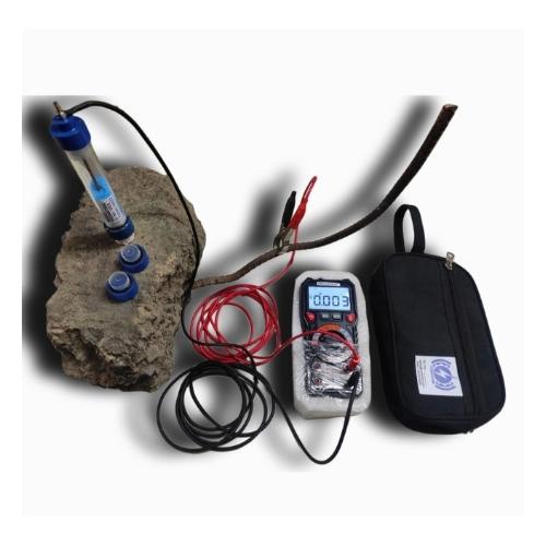
Assessing the likelihood of corrosion in reinforced concrete is crucial for long-term durability. The half cell potentiometer by Vedantrik technologies is a specialised equipment designed to evaluate the likelihood of the corrosion of the steel reinforcement embedded in the concrete structures, using a non-destructive electrochemical method. The device works on half-cell potential principle, where the difference in the potential at steel reinforcement and the reference electrode indicates the probability of corrosion. The main unit includes copper/copper sulfate (Cu/CuSO₄) electrode as the reference which is placed on the exposed surface of the concrete, and connected to the multi-meter, which is in turn connected to the rebar. The meter measures the voltage generated due to the natural electrochemical process occurring at the steel surface. More negative potential measured generally indicates higher risk of corrosion, while positive potential suggests that the steel is majorly passive and protected.The device is fully compliant with ASTM C876 and IS 516, and allows systematic mapping of corrosion-prone areas, providing data for employing preventive measures, maintenance, and structural durability assessment.
The Half Cell Potentiometer test measures the electrical potential difference to indicate whether steel reinforcement is at risk of corrosion. In Mumbai, where marine exposure and humidity are common, this test is particularly valuable. Vedantrik Technologies provides advanced half-cell potentiometer systems that deliver precise, reliable, and easy-to-interpret results. Widely used in research, maintenance, and quality control, these devices help engineers make informed decisions on repair and rehabilitation. By identifying corrosion activity at an early stage, the half-cell test prevents costly repairs and ensures structural longevity. It is a preferred choice for bridge inspections, marine structures, and high-rise developments. For dependable half-cell potentiometers in Mumbai, contact Vedantrik Technologies and safeguard your structures against premature corrosion.
Specification and Key features:
1. Voltage Range: -999mV to +999Mv
2. Temperature Measurement range 0-100 deg Celsius (Temperature sensor given as per IS 516)
3. Accuracy: +/- 1mV
4. Power Supply: pencil cell
5. Operating Temp: 0 deg Cels to 50 deg Cels
6. Auto power cut-off to save battery
7. Back light display to use in dark
8. Hold function for stable reading
9. Removable copper assembly with two side caps to improve Life of copper rod and less consumption of copper sulphate.
10. NABL calibration certificate
As a best Half Cell Corrosion Potentiometer Manufacturer in India we have supplied in Mumbai, Pune, Nashik, Aurangabad, Surat, Vadodara, Ahmedabad, Indore, Bhopal, Nagpur, Jaipur, Ludhiana, Ghaziabad, Delhi, Lucknow, Kanpur, Prayagraj, Patna, Ranchi, Dhanbad, Bengaluru, Hyderabad, Chennai, Coimbatore, Madurai, Visakhapatnam, Kolkata, and Srinagar.
Also we have supplied our Range Of Products in Dubai, Abu Dhabi, the United Arab Emirates, Oman, Saudi Arabia, Kuwait, and Iran. We also serve clients in Singapore, Indonesia, Thailand, and other international locations.
Rapid Chloride Penetration Test (RCPT)
The RCPT Rapid Chloride penetration test is one of the concrete durability tests and is a standard test for civil engineering that measures the electrical conductance of concrete specimens. This provides an electrical indication of the concrete's ability to resist the penetration of chloride ions. The Rapid Chloride Permeability Test (RCPT) is used to determine how well your concrete is resisting chloride ions against the penetration over decades.
In RCPT test chloride ions are rapidly passed through the concrete to understand the effect over decades, within 6hrs in the laboratory.
RCPT Sample conditioning requires vacuum pumps and desiccator setup with vacuum creation of less than 50 mm of Hg from the atmospheric pressure to remove the entrapped air from concrete sample to provide accurate results.
For RCPT sample preparation a concrete core of 100 mm dia and 50 mm thickness is taken and placed between RCPT assembly of two chambers containing sodium chloride (NaCl) and sodium hydroxide (NaOH) solutions.
RCPT solution preparation requires 3% Sodium Chloride (NaCl) solution for one reservoir (catholyte) and a 0.3N Sodium Hydroxide (NaOH) solution for the other reservoir (anolyte).
RCPT test Procedure involves 60 volts dc constant electrical potential for 6 hours, and current passing through the concrete is recorded with interval of 30 minutes, and total of 13 readings are logged in 6 hrs considering the initial reading as per ASTM C 1202 These values are then used to calculate the total charges passed in coulombs as per ASTM C1202.
Purpose of RCPT in Concrete testing:
The results are crucial for:
1. Assessing concrete’s ability to resist permeability of chloride ions, which is critical for concrete durability.
2. Assessing the long-term durability and predicting the service life of concrete structures, especially in environments with high chloride
exposure, like coastal regions.
3. Evaluating and ensuring the quality of concrete mixes during construction.
4. Studying the effectiveness of different concrete mix designs and admixtures.
5. Quality control tool for comparing different mix designs in terms of durability.
6. Helps in optimising concrete mix for structures exposed to aggressive environments.
Principle of RCPT test:
The principle behind Rapid Chloride Permeability Test (RCPT), as mentioned in ASTM C 1202, is based on the correlation between the chloride ion transport through the concrete, under applied voltage potential, to concrete’s porosity, which directly influences its durability performance over decades, particularly in terms of chloride induced corrosion of the embedded steel reinforcements (Rebar).
The resistivity of a concrete mix design against chloride ion penetration measured within a 6-hour test, serves as a rapid method to predict long-term durability of concrete.
The magnitude of charge passed acts as an indirect indicator of chloride ion permeability through concrete specimens. The durability and porosity of the concrete are inversely co-related, where higher charge mobility indicates high chloride permeability, consequently higher porous structure which is associated with poor durability of the concrete and vice versa. However, it is important to note that the test does not measure the total chloride diffusion or its rate, rather the total ionic conductance through the concrete, which could be affected by different factors such as temperature, degree of saturation, sample conditioning, presence of conductive materials in the mix design.
Though RCPT provides a rapid and practical method for assessing the relative resistance of the concrete to chloride penetration, its result must be interpreted with caution, when comparing the concrete specimen of different concrete mix or curing histories.
Measurement of RCPT:
The final result of the RCPT test is generally expressed in coulombs, which is the SI unit of charge, and is calculated by integrating current (in Ampere) over time (in seconds). The formula is expressed in the following way:
Charge (Q) = It . dt
However, in the actual test the current is measured at 30 minutes interval as per ASTM C1202, and total charge is often approximated numerically using a trapezoidal rule, and is used with an electronic calculator to perform the integration:
Q = 900 (Io + 2I30 + 2I60 + …… + 2I300 + I360)
Where:
Q = charge passed (coulombs),
Io = current (amperes) immediately after voltage is applied, and
It = current (amperes) at t sec after voltage is applied.
Components of RCPT:
a) RCPT Cell (Test Cell): Holds the concrete specimen and creates chambers for NaCl and NaOH solutions.
b) Concrete Specimen: The sample to be tested for chloride ion permeability. Cylindrical core of standard dimension 100 mm diameter and 50 mm thickness.
c) 3% Sodium Chloride (NaCl) Solution: Placed in the cathode chamber; source of chloride ions.
d) 0.3 N Sodium Hydroxide (NaOH) Solution: Placed in the anode chamber; completes the electrical circuit.
e) Power Supply (DC Voltage Source): Provides constant 60V across the specimen during the test.
f) Ammeter (Current Meter): Measures the current passing through the specimen to calculate charge passed.
g) Sealing Gaskets / Stainless steel O-rings: Ensure leak-proof sealing between the specimen and the chambers.
h) Electrodes: Transfer electrical current into the solutions.
i) Data Logger / Computer Interface: Records current over time to compute total charge passed (in coulombs).
Standard procedure: Overview (as per ASTM C1202)
1. Sample Conditioning (Vacuum Saturation):
Before testing, the concrete specimen (typically a 100 mm diameter × 50 mm thick cylinder) must be fully saturated to ensure accurate ion transport measurements. This is done by placing the specimen under vacuum, pressure less than 50mm of Hg from the atmospheric pressure for a specified duration (usually 3 hours) followed by immersion in de-aerated water under vacuum for at least 1 hour, then atmospheric pressure soaking for 18 ± 2 hours.
2. Cell Assembly and Electrolyte Setup:
The saturated specimen is mounted in a split test cell where one side of the specimen (anode side) is in contact with a 0.3 N sodium hydroxide (NaOH) solution. The other side (cathode side) is in contact with a 3.0% sodium chloride (NaCl) solution. Each chamber is equipped with a non-reactive electrode (usually stainless steel or brass), ensuring proper electrical contact with the electrolyte solution.
3. Electrical Testing Procedure:
A constant direct current (DC) voltage of 60 volts is applied across the specimen for a total duration of 6 hours. The initial current is recorded immediately after voltage application. Current readings are then taken at a 30 minutes interval throughout the test, generating a total of 13 readings. The current flow is due to the movement of chloride ions through the pore structure of the concrete.
4. Calculation of Total Charge Passed:
The total charge (in coulombs) is calculated by integrating the current over the 6-hour period using the trapezoidal rule. This charge represents the electrical indication of the concrete's ability to resist chloride ion penetration.
RCPT result interpretation:
The RCPT result interpretation are based on the total charge passed through the concrete specimen. The final values are obtained in coulombs which reflects the resistivity of the concrete to chloride ion transport, which is directly associated with concrete’s durability.
How to interpret the RCPT table:
The chloride ion penetrability of concrete can be evaluated based on the charge passed in coulombs. If the charge passed is >4000 C, the concrete is rated as High penetrability. A charge between 2000 and 4000 C indicates Moderate penetrability. Charges in the range of 1000 to 2000 C correspond to Low penetrability, while a charge between 100 and 1000 C is classified as Very Low penetrability. If the charge passed is <100 C, the concrete has Negligible chloride ion penetrability..
Factors influencing RCPT results:
1. Influence of Moisture Content: The test results are highly affected by the moisture content, and may lead to current fluctuations ultimately skewing the final results of the test.
2. Temperature rise: The flow of the current causes internal heating of the specimen. This may increase ion permeability and change the final results by making a concrete sample appear more permeable than it really is.
3. Influence of other ions: The presence of ions other than chloride can contribute to the total charge passed, leading to false results.
4.Effect of Admixtures: Use of chemical or supplementary cementitious materials (SCMs) like silica fume, fly ash may reduce the pore size of the concrete sample, increasing the resistance to movement of chloride ion.
Rapid Chloride Penetration Test (RCPT) Apparatus by Vedantrik Technologies:
Ensuring the durability of concrete structures has always been a major challenge in modern construction. One of the most reliable ways to assess durability is through the Rapid Chloride Penetration Test (RCPT). This test helps measure how easily chloride ions can penetrate into concrete, which is a crucial indicator of its long-term performance. By detecting permeability levels, engineers can predict how resistant a structure will be against corrosion, especially in coastal regions or environments where exposure to salt and moisture is high.
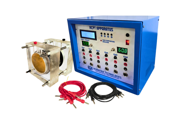
The Rapid Chloride Penetration Test (RCPT) Apparatus by Vedantrik Technologies is designed to evaluate the electrical indication of concrete’s ability to resist chloride ion penetration and to determine the chloride diffusion coefficient. It is used for predicting structural integrity, long-term durability and quality control of concrete structures.
The device features internal data logging systems through which it automatically logs the data in every 30 minutes along with automatic calculation, and report generation with graphical representation of current vs. time. It displays real-time readings from all three channels simultaneously during the test.
A key feature is its automatic shutdown after 6 hours, allowing tests to run unattended, making it ideal for overnight operation. Data is stored in internal memory or on a USB drive.
The apparatus includes an in-built Wi-Fi hot-spot, enabling wireless access to logged data from any PC, laptop, Android device, or iPhone, regardless of the operating system. It complies with national and international standards, including ASTM C1202, and offers a reliable and user-friendly solution for RCPT testing. The RCPT Apparatus comes with different channels 3, 4, 6, 8, 12.
Key Features of Vedantrik RCPT Apparatus
1. Automatic data logging at 30-minute intervals: Vedantrik RCPT apparatus is fully automated and logs the test data at every 30 minutes (also provides user defined interval option). The data is saved to internal memory.
2. Automatic calculation and report generation: Vedantrik RCPT system automatically performs the necessary calculations after the 6-hour test and can generate reports based on the logged data.
3. Graphical representation of current vs. time: Vedantrik RCPT Apparatus plots a graph of current versus time, which is a key part of the RCPT analysis. This gives a visual representation of the concrete's permeability over the test duration.
4. Uninterrupted wireless connectivity: Vedantrik RCPT equipment features wireless connectivity, typically via in-built Hotspot, which allows for remote data access.
5. Multi-device compatibility: Vedantrik RCPT wireless feature is compatible with a range of devices, including PCs, laptops, Android mobile phones, and iPhones, ensuring that users can access and share data regardless of their operating system.
6. Web-based software: Vedantrik RCPT comes with powerful web-based software that can be accessed with a range of devices, including PCs, laptops, Android mobile phones, and iPhones to access the data in real time.
7. In-built data acquisition system: Vedantrik RCPT features in-built data acquisition system that captures and stores all the test data, without the need for internet connection.
8. Stable Voltage Supply: Vedantrik RCPT is independent of input voltage, always provides stable required output voltage (60V dc for RCPT with accuracy of +/- 0.1 Volts As per ASTM C 1202)
9. Highly accurate Current measurement: Vedantrik RCPT apparatus is with accuracy of +/- 1 mA.
10. Protection: Vedantrik RCPT apparatus provides short circuit and over current over voltage protection.
11. RCPT cell Assembly: It’s easy RCPT cell assembly made up of clear transparent acrylic in two halves with flexible silicon gasket makes it seal proof and avoids use of silicon sealant.
12. RCPT Result Interpretation: RCPT result interpretation in coulombs by generating the automating result in excel sheet.
At Vedantrik Technologies in Mumbai, advanced RCPT equipment is designed for accuracy, reliability, and ease of use. Builders, consultants, and quality control labs rely on this test to ensure that concrete meets international durability standards. Since chloride-induced corrosion is one of the leading causes of structural damage, using RCPT at the right stage ensures reduced maintenance costs and extended service life of buildings, bridges, and infrastructure projects.
With a focus on innovation, Vedantrik Technologies provides testing instruments that not only deliver precise results but also support faster decision-making on construction sites. For projects that demand higher resilience and performance, RCPT becomes an essential quality control step that safeguards structural investments.
Looking for high-quality RCPT equipment in Mumbai? Contact Vedantrik Technologies today and take the first step towards stronger, more durable concrete structures.
Technical Specifications:
a) Voltage: 60V DC ± 0.1V.
b) Current measurement accuracy: ± 1mA.
c) Voltage Cell: Symmetrical poly (methyl methacrylate) Chamber suitable for NaCl and NaOH to conduct RCPT as per ASTM C1202.
d) Ambient Temperature: 20-25°C.
e) Temperature sensing with individual sensor accuracy ± 1°C.
f) Current measuring range: 1mA - 1000mA.
g) Input Voltage: 230V-265V.
As a best RCPT Rapid Chloride Penetration test system Manufacturer in India we have supplied in Mumbai, Pune, Nashik, Aurangabad, Surat, Vadodara, Ahmedabad, Indore, Bhopal, Nagpur, Jaipur, Ludhiana, Ghaziabad, Delhi, Lucknow, Kanpur, Prayagraj, Patna, Ranchi, Dhanbad, Bengaluru, Hyderabad, Chennai, Coimbatore, Madurai, Visakhapatnam, Kolkata, and Srinagar.
Also we have supplied our RCPT Rapid Chloride Penetration Test system including Dubai, Abu Dhabi, the United Arab Emirates, Oman, Saudi Arabia, Kuwait, and Iran. We also serve clients in Singapore, Indonesia, Thailand, and other international locations.
We also have Installed our RCPT Rapid Chloride Penetration Test system in IIT Mandi (Himachal Pradesh), IIT Jodhpur (Rajasthan), IIT (BHU) Varanasi (Uttar Pradesh), IIT RAM, Maninagar, Ahmedabad (Gujarat),IIT Guwahati (Assam), Nirma University, Ahmedabad (Gujarat), Veermata Jijabai Technological Institute (VJTI), Mumbai (Maharashtra), and the College of Military Engineering (CME), Pune (Maharashtra), along with various National Institutes of Technology (NITs) and government engineering colleges across multiple states in India.
Various Construction company like Larsen & Toubro (L&T), Ashoka Buildcon Limited, Adani Realty Limited, Kalpataru Limited, NCC Limited , National Council for Cement NCCBM, Quality Council of India (QCI), Megha Engineering and Infrastructure Limited (MEIL), TCR Engineering Services, Global Lab.


 Chat with us
 Chat with us